The proliferation of nonlinear electric loads is threatening electric grid reliability in industrial, commercial and residential premises. What are nonlinear loads? They are any piece of electric equipment whose impedance changes with applied voltage. Examples in industrial applications include large variable-frequency motor drives or high-current arc welders. Switched-mode power supplies in server farms, office equipment and all types of consumer electronics are also nonlinear loads.
The changing impedance of a non-linear load causes currents drawn to be non sinusoidal; therefore, these loads cause harmonic currents, which are currents that are at a frequency that is an integer multiple of the fundamental frequency (the fundamental frequency is 50 or 60 Hz, depending on region).When these harmonic currents propagate through the system impedance, distortions called harmonic voltages can occur on the supplied voltage (as you might guess, harmonic voltages are voltages that have a frequency that is an integer multiple of the fundamental frequency).
When these current and voltage harmonics occur, they can damage other electric equipment plugged into the grid, at both the utility and other electricity consumers. It is therefore the responsibility of electricity providers and large energy consumers to minimize the impact of nonlinear loads and their associated harmonics. The first step toward this is to monitor the grid for the presence of harmonics. Adding total harmonic distortion (THD) measurement to energy meters is a good place to start.
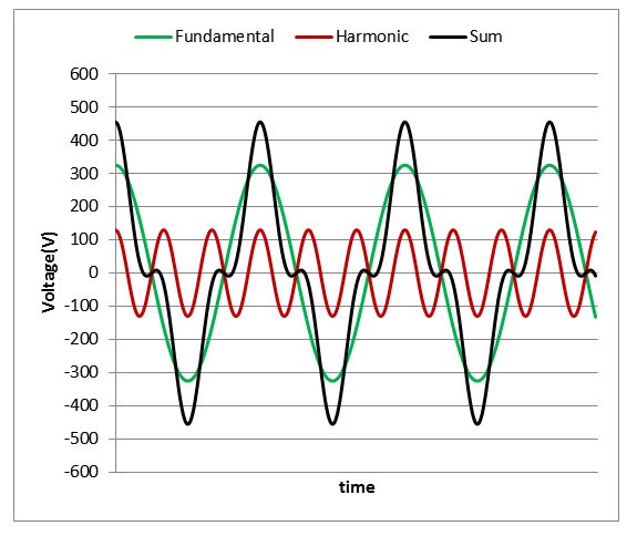
Before delving into the details on how to calculate THD, let’s first discuss the basic concepts of harmonics. The first thing to note with respect to harmonics is that you can decompose the waveform resulting from harmonics into a sum of sine waves. In the decomposition of the resulting waveform, the component at the nominal frequency is referred to as the fundamental frequency. Sine-wave components with a frequency that is an integer multiple of the fundamental frequency are called harmonics, where the nth harmonic component corresponds to the component at the frequency of n times the fundamental frequency. In Figure 1, you see an example of how a third-harmonic voltage component and a fundamental voltage combine to create a new waveform that deviates from the sinusoidal shape.
Figure 1: Example Voltage Waveform with Third Harmonic Component Present
When harmonics are present in the voltage and current, you can take the corresponding root-mean-square (RMS) measurement by using the waveform samples of the resultant waveform (as an example, the black waveform in Figure 1) and plugging it into the standard RMS equations, Equations 1 and 2:
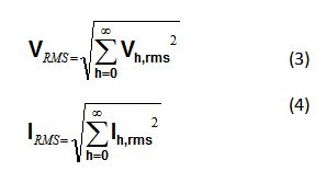
If you know the RMS value of each harmonic component and the RMS value of the fundamental, then you can alternately calculate RMS by taking the square root of the sum of squared RMS values of each harmonic component and of the fundamental, as shown in Equations 3 and 4:
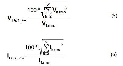
You can calculate the THD parameter as a measure of the total harmonic content in a signal. There are two common definitions of THD. In the first definition, as defined by IEC 61000-4-7, THD is the RMS value of the sum of all harmonic components (Vh,rms for voltage, Ih,rms for current) up to a specified order (N) to the RMS value of the fundamental component (V1,rms for voltage, I1,rms for current). Equations 5 and 6 are the formulas for voltage and current THD, respectively:
This definition of THD is more common in energy measurement systems and may result in a THD value that is above 100% when the contribution of the fundamental signal is less than the total contributions of the other harmonics.
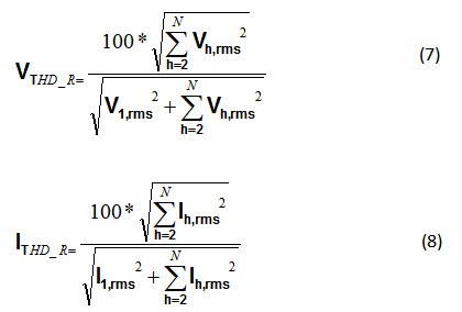
In the second definition of THD, THD is the RMS value of the sum of all harmonic components (Vh,rms for voltage, Ih,rms for current) up to a specified order (N) to the total RMS value (V1,rms for voltage, I1,rms for current). This total RMS value includes the effects of the fundamental as well as the other harmonics. Equations 7 and 8 are the corresponding formulas for voltage and current THD, respectively:
For the second definition of THD, the value will always be less than 100%, since the total RMS value is used as the denominator instead of just the fundamental RMS value.
When testing for THD accuracy, note the definition of THD used, as the two different definitions will lead to two different values.
In both definitions, you must find the RMS value of each harmonic component. Calculating these RMS values requires fast Fourier transform (FFT) operation. Depending on the selected metrology processor, this may be computationally expensive. In the next installment of this series, I’ll describe a less computationally expensive way to estimate THD.
Additional resources:
- Learn about power quality in the following blog, "Power quality is essential to a smarter grid."
- Download the following reference designs related to THD:


