

Last week we concluded that the very accurately matched resistors of an integrated difference amplifier were crucial in getting the needed common mode rejection. Review it here. But...
There is one relatively common case, however, where 1% resistors and a good op amp can make an adequate difference amplifier. When measuring current with a shunt on the “low side” of the load, the common mode voltage is generally quite small. You might even be tempted to use a standard non-inverting amplifier to measure the voltage across the shunt since the shunt voltage is ground-referred. But still there is likely to be a small voltage drop on stray ground resistance. You probably need a differential measurement that Kelvin senses the voltage, making a four-wire connection on the shunt.
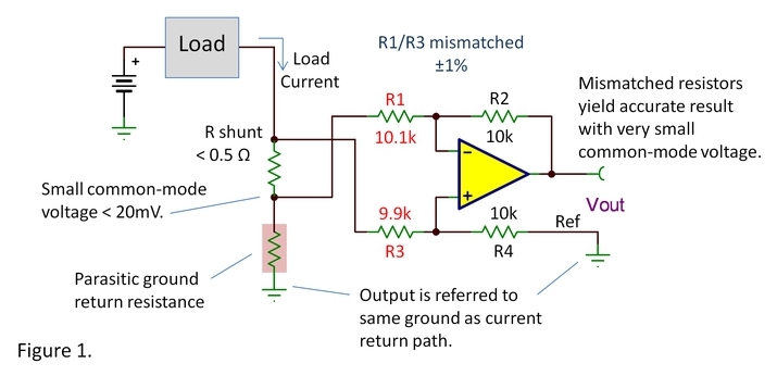
Because the voltage drop on the stray or parasitic resistance is small, a difference amplifier with modest common-mode rejection may well be accurate enough. As discussed last week, if two of the resistors in this do-it-yourself difference amp are mismatched by ±1% you will yield a 100x attenuation of the error voltage on the stray resistance or 40dB common-mode rejection.
If the only current flowing in this parasitic stray resistance is the measured load current, the error created is simply a gain error on the desired signal. It might be a positive or negative gain error depending on the direction of the resistor mismatch. But frequently there are other currents flowing on the board or in the system that may create a voltage unrelated to the measured load current.
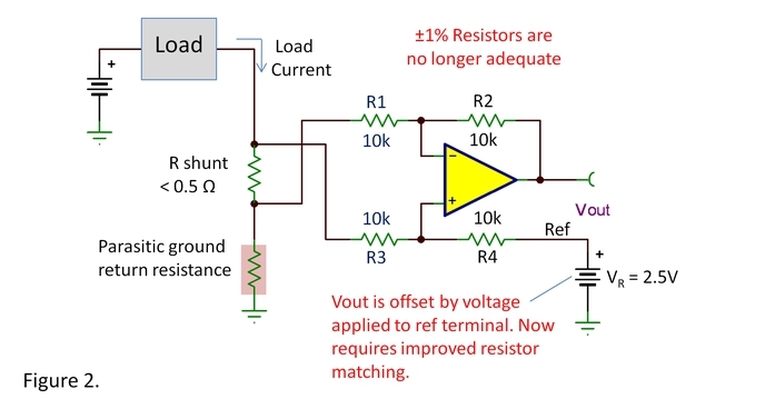
In yet another variation, figure 2 shows a low-side measurement case where you again probably need very accurate resistor matching. Here, the output voltage is offset with a reference voltage applied to the “Ref” terminal of the difference amp. This is often done to raise the output voltage above zero to more accurately process signals near zero load current. This is really much like the case last week. The offsetting voltage is much like the larger common-mode input voltage discussed last week. You need precise resistor ratios (such as with the INA133) to assure that Vout is accurately referred to the 2.5V VR.
The simple difference amplifier is a valuable circuit tool and every analog designer should understand its common-mode rejection properties and resistor matching issues. But be aware that we have a wide range of specialized ICs for measuring currents flowing through a current shunt. TI broadly classifies these as current shunt monitors. They are capable of measuring the current through resistors at voltages ranging from -22V to +80V. Some also measure the voltage in addition to current and calculate power. Check out these devices using this current shunt monitor selector guide.
Thanks for reading,
Bruce
Bonus material—The Excel formula below calculates the nearest standard 1% resistor value. Copy all of the blue text below and paste it into Excel cell A2. Put a resistance value in cell A1 and A2 will display the nearest 1% value. You can copy A2 to other cells and it will calculate the resistance in the cell to its left.
=IF(A1>(INT(0.5+100*POWER(10,IF(96*(LOG(A1)-INT(LOG(A1)))-ROUND(96*(LOG(A1)-INT(LOG(A1))),0)<0,ROUND(96*(LOG(A1)-INT(LOG(A1))),0)-1,ROUND(96*(LOG(A1)-INT(LOG(A1))),0))/96))* POWER(10,INT(LOG(A1))-2)+INT(0.5+100*POWER(10,(IF(96*(LOG(A1)-INT(LOG(A1)))-ROUND(96*(LOG(A1)-INT(LOG(A1))),0)<0,ROUND(96*(LOG(A1)-INT(LOG(A1))),0)-1,ROUND(96*(LOG(A1)-INT(LOG(A1))),0))+1)/96))*POWER(10,INT(LOG(A1))-2))/2,INT(0.5+100*POWER(10,(IF(96*(LOG(A1)-INT(LOG(A1)))-ROUND(96*(LOG(A1)-INT(LOG(A1))),0)<0,ROUND(96*(LOG(A1)-INT(LOG(A1))),0)-1, ROUND(96*(LOG(A1)-INT(LOG(A1))),0))+1)/96))*POWER(10,INT(LOG(A1))-2),INT(0.5+100*POWER(10,IF(96*(LOG(A1)-INT(LOG(A1)))-ROUND(96*(LOG(A1)-INT(LOG(A1))),0)<0,ROUND(96*(LOG(A1)-INT(LOG(A1))),0)-1,ROUND(96*(LOG(A1)-INT(LOG(A1))),0))/96))*POWER(10,INT(LOG(A1))-2))
Go ahead... try it!
