This thread has been locked.

If you have a related question, please click the "Ask a related question" button in the top right corner. The newly created question will be automatically linked to this question.

LM4861 Motorboating

Other Parts Discussed in Thread: LM4861, LM386, LME49720, TL082

Hi

We have a design with a LM4861 that becomes unstable when it is driven to the clipping limit. When the about 6 Hz self oscillation has started it can be stopped by disconnecting the loudspeaker. During the oscillation the amplifier output DC-voltage drops from the normal 2.5 V to about 1 V and it gets very hot.Has anybody seen a similar behavior and found out how to prevent it?

  • Hello Klaus,

    I've seen a similar behaviour in a circuit using LM386 but the problem was a missing 0.1uF supply bypass capicitor, other problems could occur with unity gains (-1), because of the phase margin (if the phase reaches 2pi*n) meeting the Barkhausen criterion you may have oscillation, but I think this amplifier is unity gain compensated (the phase is kept far from 2pi*n). The 0.1 uF capacitor should be placed near the supply pin in the PCB layout and ground paths must be short and wide to prevent signal injection to ground and ground loops (because real conductors are not ideal so when current passes thru it the voltage is above 0), the input ground must be connected on the ground path near the IC ground.

    Best regards,

    Daniel Almeida

  • Hello Daniel

    Thank you for answering. We already have a 0.22 uF sitting right next to the amplifier, then we have 52 uF a few inches away and then we have 86 uF on the other side of a 13 mOhm FET. The LM4861 is unity gain stable, but we run it with a gain of 80, so this should not cause the oscillation either.

    Best regards

    Klaus Moelholm

  • Hello Klaus,

    Do you have tried to reduce the gain to 20 like the circuit in figure 3, using the same values of the components?

    You should also use a voltage regulator with the desired voltage (always between the operational limits).

    You can then add a 4 V/V preamplifier like the LME49720 if you don't have specific PCB space requirements.

    How do you do to control the volume of the amplifier, sometimes if you use a pot at the input oscillation could occur, so it's better to use a voltage follower (voltage buffer).

    If you don't want to take this drastic measures you could try to add an audio buffer at the input, a preamplifier with vg = 1 V/V, also with LME49720 or a cheaper multipurpose opamp like TL082, I've solved one of my oscilation problems, driving an ST amp with a TI opamp TL082.

    A sugestion of a very versatile regulator if you already don't have one is the LM338T or LM338K, with adjustable output voltage and a large output current, I've one and it's one of the best linear regulators I've used.

    Can you post the schematic of your circuit?

    I hope that this message helped you,

    The best luck for your project,

    Best regards,

    Daniel Almeida

  • Klaus,

    Is the fet fully turned on? Is your supply capable of providing enough power?

    Can you capture a scope shot of the voltage at the VDD pin to make sure it's stable?

    -d2

  • We already use a IR3473 voltage regulator.

    We don't need a preamplifier, the current gain is set to high.

    The volume is controlled digitally in the SGTL5000 codec that is driving the LM4861.

    You can se the schematic here: 0820.LM4861.PDF

    Best regards

    Klaus Moelholm

  • Don,

    Yes the FET is turned fully on, it is turned on as a part of the power on sequence. The supply can provide 6A.

    The voltage at the VDD pin is normally flat, during oscillation a small variation (about 20mV) coinciding with the oscillation can be seen.

    Best regards

    Klaus Moelholm

  • Klaus,

    OK, sorry, we always have to rule out the most obvious things first... 

    What about the freq of oscillation? Can you post some scope shots?

    -d2

  • Don,

    The oscillation frequency is about 6 Hz. When seen on the scope it looks like the amplifier oscillates between shutdown mode and active mode because the DC-voltage on both outputs drops from the normal 2.5V to about 1V.  I am sorry but I am not able to recreate the error at the moment, so I can't post scope shots of the oscillation.

    Best regards

    Klaus Moelholm

  • Hello Klaus,

    Thank you very much for sending your schematic, it seems a very interesting project, the amp is usb powered?

    In this post I've wrote some sugestions for your design:

    You should try to monitor the voltage on the shutdown pin during the oscillations, the oscillation could be caused by signal injection on ground plane influencing the shutdown circuits, the ground plane should be wide and short and have a large aluminium electrolytic capacitor to lower the impedance of this tracks during high loading conditions.

    Other question you are using the amplifier as an inverting adder amplifier?

    Atention for this circuit the expressions are: Vo1 = -Rf*((Vin1/Rin1)+(Vin2/Rin2)+(Vin3/Rin3)+(Vin4/Rin4)) + Vos [V]

    Vo2 = Rf*((Vin1/Rin1)+(Vin2/Rin2)+(Vin3/Rin3)+(Vin4/Rin4)) + Vos [V]

    Vo1 and Vo2 in respect to common (gnd), Vo differential

    You should connect Vo2 at plus terminal of the speaker, and Vo1 at the minus speaker terminal, to avoid phase shift 180º or pi at the output sound.

    Vo = Vo1 - Vo2 = -2*Rf*((Vin1/Rin1)+(Vin2/Rin2)+(Vin3/Rin3)+(Vin4/Rin4))

    Vos aproximately Vcc/2, to maximise the output excursion.

    This expression are only valid for AC signals.

    The expression has the 2 times, because the amplifier is differential.

    Vin1 = BEEP_CPU

    Vin2 = BEEP_FPGA

    Vin3 = LINE_OUT_L

    Vin4 = LINE_OUT_R

    Rin[1...4] - input resistors for the above signals.

    I think that Vin3 and Vin4 should have a different capacitor and not the same capacitor, and the resistors should be added after the capacitor (figure attached), but this aspects are only sugestions.

    fL = 1/(2*pi*Cin*Rin), for each input

    Notes: All these expressions are ideal, in real devices the expressions can vary. The ground of the signal generating devices must be connected to the same common (gnd) as the amplifier.

    Thank you very much for your atention,

    Best regards,

    Daniel Almeida

  • Hello Daniel

    The amp is powered by a IR3473 6A switch mode power supply.

    At the moment we are not able to repeat the error, but if we see it again i will check the shutdown pin. The ground plane consist of 4 layers of copper . According to the data sheet the shutdown pin is a logic input and should therefore be fairly insensitive to noise on the pin.

    Yes I am using the amplifier as an inverting amplifier with 4 signal sources.

    Thank you for your comments.

    Best regards

    Klaus Moelholm

  • Hello Klaus,

    Personally I think that switched mode power supplies are not very good to use with audio applications, but if there isn't another option.

    Best Regards,

    Daniel Almeida

  • Hello Daniel

    There are no other options.

    Best regards

    Klaus Moelholm

  • Hi, Klaus,

    Nearly every single customer application I work on uses an SMPS for power, as you stated, realistically, there are no other options for a mass produced product, especially if you want to sell it world-wide...

    6 Hz... That almost sounds like maybe it was the thermal protection kicking in.

    If you run across it again, please try to capture some scope shots. I'd like to see the power supply (at the pin of the LM4861), the outputs (OUT1-OUT2 differentially), and the input signal.

    -d2

  • Hi Don

    I also think that it is the thermal protection circuit that somehow self-oscillates.

    I promise that if we see it again, we will get the documentation while we can.

    Best regards

    Klaus Moelholm

  • Klaus,

    OK, great! I'm going to close out this thread, then.

    -d2

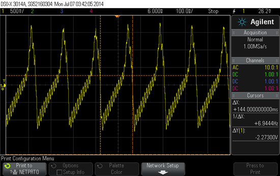
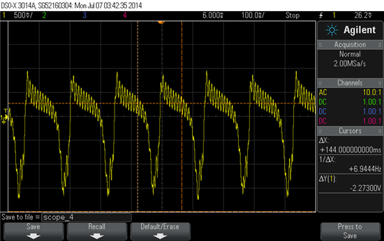
  • Here are some scope plots I captured of this event.

    Vo1 (pin5)

    Vo2 (pin 5)

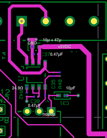
    The Layout looks like this:

    The shutdown pin:

    I tried this with the 24.9 Ohm resistor installed and with a hard short.

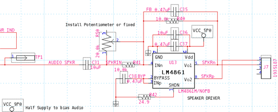
    The schematic:

    The capacitor  C35 (in the feedback circuit) is a 30pF.  I tried without the feedback cap too.  Same result.  My intention was not to use but I tried just in case.R50 (the potentiometer) is not installed.  There is a DC (4.5 V) on TP1 plus some noise.  I was able to get good sound at some point but the circuit is sometimes dominated by the motor boating.

     My power supply does get dragged down while the motor boating is active but NOT during normal play.  I have not, yet, determined the instigating event.  I added a 47uF cap on top of C36 (the 10uF) for additional bulk capacitance.

    I appreciate any assistance ensuring this does NOT occur.  

    Thanks,

    Wayne

  • I have also heard a higher pitched "squeal".  It seems to occur when I am probing the circuit or a transient occurs.

  • Oh... one other thing... the circuit driving the input to the speaker amplifier circuit (the LM4861) is a summing amplifier using a TLC072IDR (opamp) using a 9V rail and a 4.5V DC offset.  I am wondering if this is a potential problem. 

  • Hi

    I use a 1uF decoupling capacitor on the BYPASS pin (2). Maybe this makes a difference? You could also try to improove the power supply by adding more low ESR decoupling capacitance or maybe use a power supply with lower impedance and higher current capability.

    Best regards

    Klaus Moelholm

  • Klaus,

    I have started with a 10uF bulk and 0.47uF decoupling caps (both very close to the power pins of the IC).  This exhibits the problem so I will try adding a very large bulk cap (8200 uF, electrolytic) to see if that removes the problem.   I will report back after I get make the change

    thank you for your response 

  • OK.  I have a solution.  It was in some of the previous posts.  In my case the AC adapter I was using as a power supply was not good enough to provide the instantaneous power needed by the speaker driver at transient events.

    The power scheme is like this:

    12V -> 9V -> 5V

    the 12V was a 300mA nominally 12V supply

    The 9V supply created a 4.5V half supply reference for use in the analog circuit.  Then the current demands went up the half supply moved which created a false "signal" which made the speaker drive attempt to follow and use more current.  This went until the supply collapsed and process started over.  When I run on an 3A , 12V bench top supply there is no problem.

    I checked the current meter on the supply and a 500mA AC wall wart will do the trick!