This thread has been locked.

If you have a related question, please click the "Ask a related question" button in the top right corner. The newly created question will be automatically linked to this question.

calculating input impedance with wye voltage divider in non-inverting op amp

Other Parts Discussed in Thread: OPA2134

Hi there

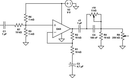
I need some expert advice on calculating the input impedance of this buffer preamp. I have found several conflicting methods, and would like to publish accurate specs.

I have seen the voltage divider rule i = 1/ (1/R6 + 1/ R7)

and some others have said to take the value of the first resistor to ground R5 at 1 meg

a prominent builder lists a similar arrangement as 1 meg in his specs.

This is a single stage and  single supply ac coupled voltage amp buffer for piezo transducers, and preamp for magnetic pickups, with the bare minimum parts count.

I would ideally like 1 meg input impedance. And I dont really want to push up the values of R5 & R6 for introducing more johnson noise before the amp

R7 is necessary not only for the obvious current limiting, but especially to flatten out the frequency response and keep the phase shift to a minimum ... at a cost of a few db

I have used 1K for R7 in several previous designs but sims have shown flatter response and far better phase shift at 10K.

So what is the proper method for calculating input impedance with the 3 resistor wye divider?

many thanks!

  • also:

    R2 is actually a 100K trimmer for gain adjustment

  • Hi Willie,

    If we assume that the open loop gain of the buffer being used is very high (which it should be), and with a closed loop gain of 1 (as it is), then the input impedance looking into C1 from the source would be:

    R5//R6 + R7 = 510k ohms

    If you want the input impedance to be 1M, then R5 = R6 = 2M would do the trick.

    Best Regards,

    JD

  • Thanks John,

    I am using an opa2134, so the open loop gain is 120db. I am going to pop in a couple of 2 meg resistors in the divider  and see how it does. The closed loop gain varies from 1 to 11 with a 100K pot

    .... At higher gain the 2 X 2M resistors thermal noise would be 4 times higher at unity gain, and 44 times the noise at full gain... so this may introduce a good bit of white noise.

    I am also wondering,

    if I use the unused half of the opa2134 in front of the circuit as a unity gain voltage follower (ac coupled) with it's output hardwired back into the inverting  input, if it would exhibit the rated high input impedance of the op amp at 10^13 Ohms? ...and then just set its output impedance higher before the second stage.

    Perhaps with the same 1uf capacitor in series in the feedback loop as the input (to minimize offset voltage between the inputs  ) the extra cap could get weird as it would create a -45 phase shift (lag) in the negative loop, just as the ac coupling cap introduces the + 45 phase shift (lead) in the non-inverting input below the corner frequency, if I am correct. This in theory should cancel the phase shift of the ac coupling cap though. 

    Thanks for the help

    Willie

  • Hi Willie,

    Ah, good part to use; FET input. Because of this, when you use the amplifier at the higher gain, you shouldn't have an impact on the overall solution input impedance; ie there won't be any loading from the op amp.

    Let me ponder on the buffer idea and see if there is a way to reduce the overall noise.

    I don't think you want a cap in the feedback loop.

    Best Regards,

    JD

  • John,

    Thanks for your pondering. The cap in the feedback loop is indeed a bad idea. Any large phase shift in the loop , even to correct  the shift in the non inverting input seems to cause the Op Amp to go to zero output.

    And the buffer would present ultra high impedance, but still has to be biased to virtual ground between the rails of the single supply, and any divider in front will drop the input impedance.... so it's defeating the purpose in a single supply design.

    Perhaps the other 1/2 of the opa2134 could be used as a rail splitter and it's output replace the resistive divider in the circuit. I believe however the rail splitter would present a very low impedance to the source through C1 however. Or  it may be possible use a separate op amp to flip the phase of the 9V supply to -9V (roughly) to refrence the audio chip's -V input pin.

    ...and possibly there is a solution to reference virtual ground to the inverting feedback loop and keep the resistance off the non-inverting input .

    I believe the ideal solution is to leave this schematic intact for single 9v supply and increase the resistive didvder to 1 meg as it works very well for multiple piezo transducers and folks rave about its tone and lack of noise.

    ...and then design another pre that is a bi-polar supply, useing two 9V batteries or phantom power to power the chip without needing a resistive divider or rail splitter virtual ground, that would allow for the ultra high impedance input.

  • Hi Willie,

    Sorry for the delayed reply. It sounds like you have a number of options that you are considering. I'm not sure if you have a solution yet or not, but you might want to briefly investigate this option. It may work; ie have 1M input impedance and be lower noise.

    Best Regards,

    JD

    0336.OPA2134_Single_Sup_HighInZ_012813.tif

    8640.OPA2134_Single_Sup_HighInZ_012813.tif


  • JD

    Many thanks for your help, and for the suggestion above. I will plug it into the sim and then mock it up. I am still working on the most efficient design for a buffer pre. I hope to have a new design soon that incorporates balanced out, and some more features. 

    I added 2 more 1 meg resistors in series with the 1 meg bias resistors to the original circuit, and a dpdt switch to bypass 2 of them for selectable impedance. And I beefed up the output coupling cap to 2uf. The frequency response and phase shift is nearly flat at 2meg to each rail. The original 510 ohm setting retains the lower noise and is matched nicely for a specific pickup manufacturer's transducers.

    It is probably not ideal for offset current, but it sounds quite good. I have ordered a production run of PC boards before all of Asia shuts down for 2 weeks for the New Year holiday.

    My Humble Thanks JD !