This thread has been locked.

If you have a related question, please click the "Ask a related question" button in the top right corner. The newly created question will be automatically linked to this question.

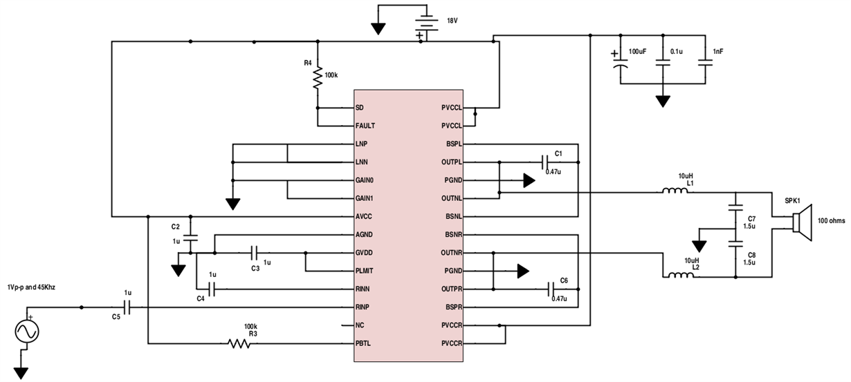
TPA3113D2 SCHEMATIC review , it's not working with me

Other Parts Discussed in Thread: TPA3113D2, TINA-TI

Hello Everyone , 
I hope someone could help me with with finding why the amplifier ""TPA3113D2" is not working with this schematic. I tried following the datasheet connection diagram for a single ended side input in page 19. I built up the schematic and it didn't work , I tried different TPA3113d2 but still it didn't work. 

The amplifier needed to drive an ultrasonic transducers array with 100 ohms load resistance ... 
any help would be highly appreciated :)
Kamal
  • Hello Kamal,

    What do you mean by "it does not work"? I am going to presume the transducer is not output what you expect? Which leads to the next question, what *is* it that you expect?

    I know TI have a family of DRV products that may be better suited than a class D amplifier. You are looking for the high efficiency of PWM?

    -Ken

  • Ken Dillinger said:

    Hello Kamal,

    What do you mean by "it does not work"? I am going to presume the transducer is not output what you expect? Which leads to the next question, what *is* it that you expect?

    I know TI have a family of DRV products that may be better suited than a class D amplifier. You are looking for the high efficiency of PWM?

    -Ken

    Hello Mr. Dillinger, 

    First , thanks for your response, I highly appreciate it .. I mean it's not giving me any output. This setup has gain of 20 dB and I have been unable to find it out why the amplifier is not giving any output .. there's something wrong, I couldn't figure as hard as i am still trying .. 

    anyhelp would be highly appreciated.. 

    Kamal

  • Hello Mr. Dillinger,

    First , thanks for your response, I highly appreciate it .. I mean it's not giving me any output. This setup has gain of 20 dB and I have been unable to find it out why the amplifier is not giving any output .. there's something wrong, I couldn't figure as hard as i am still trying ..

    anyhelp would be highly appreciated..

    Kamal
  • No output would mean you are seeing no PWM waveform on a scope. Since the TPA3113 is a class D amplifier, the output is always switching even with no input signal. Even in shutdown or mute most class D amps that I have seen will have a 50% duty cycle with a net voltage difference of 0V across the load.

    So:

    1) Please clarify what you see on the output on a scope. PWM or no waveform at all.

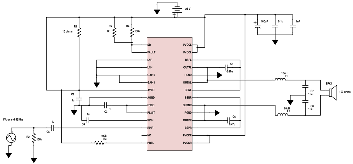
    2) You are shorting the 10 ohm resistor R1.

    3) Measure the FAULT and SHDN pin. Is it low or high?

    4) R5 is not needed in your schematic. The datasheet example assumes a GPIO.

    -Ken

  • Hello Mr. Dillinger , 

    Thanks a lot for your response . it is highly appreciated ..

    Here are the answer for these points :

    1- I see no waveform at all. 

    2- I took off the 10 ohms out of the circuit and I am attaching how the new circuit looks like ..

    3- I measured the Shutdown pin and Fault , they were high in both circuits I tried during testing.

    I am attaching two schematic I used , both, it didn't work. I changed the value of AVCC in one of them and sat to 5 V according the reference design simulation in Tina-TI provided by ti.com

    I had multiple amplifiers.As i was testing , I switched them .. only one of them , got hot very quick and i disconnected it right away.. and only this one keeps getting hot as soon as i hook up the circuit .. 

    Thanking you in advance,  and I highly appreciate taking some of your valuable time into this..

    Kamal 

  • What is the test setup? Is this on a breadboard with a socket, the TI EVM, or your own PCB?

    If 2 parts are getting hot then the thermal protection should kick in and no damage should occur to the devices - if we presume the output is being driven or if there is a short. I would imagine short circuits on the output would draw current through the output stage, increase power dissipation, and then shutdown due to the thermal protection of the device.

    Time for a deconstruction:

    1) Ensure your PSU is off.

    2) Use a device that was initially getting hot - put it back in the socket or PCB if that's the case.

    3) Disconnect the transducer and leave your input signal 0V.

    4) Check all of your pin connections for solder bridges and cold joints (presuming a PCB); ensure the device is set correctly (presuming a socket).

    5) Turn on your PSU and, 

    a) If the device is getting hot, it may be damaged. Swap it with a new part.

    b) If the device is not getting hot, measure the output pins. You should see a PWM output. Check your FAULT pin as well.

    -Ken