This thread has been locked.

If you have a related question, please click the "Ask a related question" button in the top right corner. The newly created question will be automatically linked to this question.

Question about resister step of TAS5766M

Guru 19485 points
Other Parts Discussed in Thread: TAS5766M

Customer resister step is below.

(Default setting)

Step       w/r          reg add       data

1            w            00                00    ⇒Page 0

2            w            02                10    ⇒Standby Mode

3            w            03                11    LR Mute:On

4            w            xx                xx      (Writing coef A, B, Instrunction memory)

5            w            00               00     ⇒Page 0

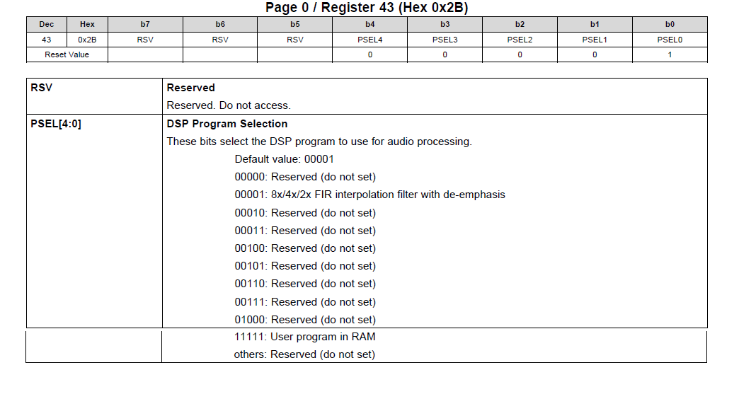
6            w            2B               1F    DSP Program selection →USER Program

7            w            00               2C    ⇒Page 44

8            w            01               00     Adaptive mode :Disable

9            w            01               04     Adaptive mode :Enable

10           w            00              00     ⇒Page 0

11           w            02              00     Standby Mode disable

12           w            03              00     LR Mute:Off

end

When started thereafter Step-5 of TAS5766M, it was the following movement.

(1) Even if Standby is disabled, a sound doesn't out.

(2) Even if 0x2B is returned to 01(Default), a sound doesn't out.


 I think that the cause of (1) are no writing in CRAM.

Please let me know about cause and measure of(2).


Best regards,

Satoshi

  • Hi Satoshi-san,

    Sequence seems correct. In fact, proper sequence is the one generated by dump definition file (.reg).

    This is in customer board, correct? Could you share schematic?

    Is SCLK being provided to TAS5766M? If not, there are some additional registers that would need to be written.

    Regards,
    J-

  • Dear Arbona-san

    Thank you for reply.

    This is customer board, schematic is equal to datasheet's Figure-61.

    (LC filter value is a little different because customer use 6Ω speaker)

    SCLK is providing to TAS5766M.

    Additional information about Step 6 : add 0x2B.

    ・When Step-6 : add 0x2B set to  data "0x1F", a sound doesn't come out.

    ・When 0x2B changed "0x1F" to "0x01", and StandbyMode was made Off⇒On, a sound came out again.

    ・The timing by which data of 0x2B influence is standby-OFF/ON, is it correct?

    Please let me know a relation between Page 0, 0x2B (DSP Program Selection) and standby.

    Best regards,

    Satoshi

  • Hi Satoshi-san,

    The script below will perform a software reset first. This ensures C-RAM is completely reset to its default state which is required for DSP Mode 1. Running this script should result in audio playback every time if I2S is present. Let me know if this works always and then we'll proceed with the second part of the issue which is the User Program.

    #-------------------------------------------------
    # Reset
    #-------------------------------------------------
    # Select Page 0
    w 98 00 00
    # Set the device into Powerdown
    w 98 02 11
    # Reset Device
    w 98 01 11
    
    #-------------------------------------------------
    # Sleep
    #-------------------------------------------------
    # Select Page 0
    w 98 00 00
    # Set the device into Standby
    w 98 02 10
    
    #-------------------------------------------------
    # Select DSP Mode 1
    #-------------------------------------------------
    # Select Page 0
    w 98 00 00
    # DSP Program = Mode 1
    w 98 2B 01
    
    #-------------------------------------------------
    # Wake
    #-------------------------------------------------
    # Select Page 0
    w 98 00 00
    # Wake from Standby
    w 98 02 00
    

    Regards,

    J-

  • Satoshi-san,

    Another thing, when writing burst writes make sure the MSB of the register byte is set to '1'. In fact you can always use MSB = '1' even for single byte write, so I recommend it for both cases. For example, to write register 2, send 0x82 as register byte.

    Regards,
    J-