This thread has been locked.

If you have a related question, please click the "Ask a related question" button in the top right corner. The newly created question will be automatically linked to this question.

200KHz ultrasonic driver

Hi guys, 

I am looking for a solution for driving a 200KHz ultrasonic transducer. The maximum that the transducer can handle is 500Vpp. So I am trying to boost an input square wave pulse to about 200Vpp~300Vpp. Currently, I am using a TI ultrasonic flow meter evaluation board. It can boost a 3.5Vpp to 30Vpp. Then, I used a 200KHz pulse transformer to boost it to 150Vpp. But the boosted square wave has a huge distortion. 

My goal right now is to get ride of that boost board. In other words, I want to boost 3.5Vpp to about 300Vpp. I think the pulse transformer is still a potential choice, but it requires a relatively high current, which is about 1 A (peak current is 3 A according the transformer's datasheet).

The question: 

Is there any way I can directly amplify 3.5Vpp to 300Vpp without using transformer? For example, any high output voltage power amplifier? 

Or if I will keep using this transformer, what chips I should use to boost the current and voltage to the desired level that transformer needs? The primary side voltage and current of transformer is 3V to 24V, Ipeak = 3A.

Thanks for the help!

Jingyuan Liang

  • Hi, Liang,

    Sorry for the delay in getting back to you.

    Unfortunately, we do not have any information on this type of application.

    -d2
  • Hi Don, 

    Thanks for your reply though. Yeah, I have to use other method to get my goal. TI just had a new high voltage piezo driver, but its bandwidth is too small and it does not fit my application. I really hope TI can produce an ultrasonic high voltage driver in future, because I looked all other companies product and they don't have the similar product available. 

    Thank you!

    Jingyuan Liang

  • How capacitive is the transducer?

    A 2 -300KHz SQUARE wave into a piezo ceramic element is a big ask, and you really need to specify the required bandwidth and how the admittance/susceptance plot behaves over that bandwidth.  

    The usual approach for sonar (which typically runs about an octave of bandwidth on transmit (sometimes much less) is to tune out the fixed capacitance of the transducer with the inductance of the transformers secondary and to extend the bandwidth by preceding this with some sort of L/C/R matching network (Usually an L match with a series resistor to control the Q at the band edges).

    Note that the narrow transmit bandwidth implies a sine wave in the water, as you would need very much more bandwidth to accommodate sufficient harmonics to make something that looks like a square wave (And that is before you get into the transducers group delay issues). 

    As far as drive to the input side of the matching network is concerned, full bridge is fairly commonplace, with the amplitude being controlled by varying the DC bus voltage, it is difficult to see that there is much traction here for special purpose sand, power mosfets, gate drivers, and the usual trimmings are the normal approach.

    Regards, Dan.

  • Hi Dan, 

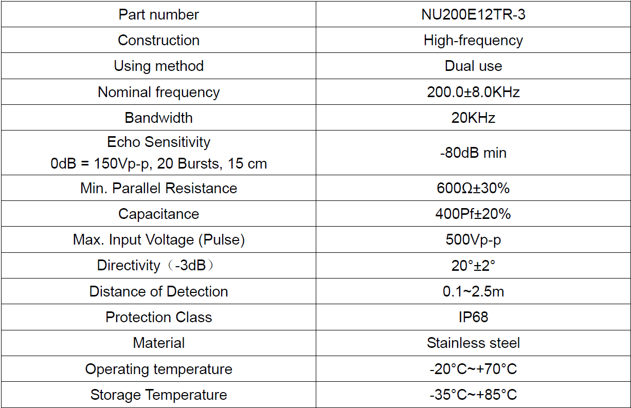
    Thank you so much. It is very helpful. Below is a chart of characteristics of the transducer I am using. 

    I couldn't find any available chip to directly driving these sensors. Right now, I am using the ultrasonic driver evaluation board made by TI to drive the low voltage square wave to about 35Vpp square wave (It uses gate driver). Then, I passed this square wave into a 1:10 switching mode transformer. It can give me up to 240Vpp output voltage and it is a sine wave. It will be fine to drive the transducer by using either square wave or sine wave. 

    I read about your paragraph on matching the load impedance, but I don't really know how to do that. I am still a student and don't have any experience on this before. Could you please give me some information on this, any website or books I can look up? 

    So I am thinking about using my current method to do the driving. There was one interesting thing I found is that when I directly connect the transducer to the secondary of the transformer, it gave me 150Vpp instead of original 240Vpp if I use scope probe to measure it. Meantime, the 150Vpp wave form has a great distortion. There is a quite bit amount energy present at about 100KHz besides 200Khz. However, if I connect a about 10K resistor after the secondary of the transformer and before connecting to the transducer in series, the 100KHz energy disappeared. As I increased the resistor's value, the peak to peak voltage increasing. As i decrease the resistor's value, the peak to peak voltage decreasing and the 100KHz energy begin to show up at certain resistor value. 

    Is this about the impedance matching thing? 

    Thank you!

    Jingyuan

  • What you have there is a narrow band transducer, which electrically looks like this by my back of an envelope calculations:

    The series RLC defines the bandwidth and center frequency and C2 in represents the fixed capacitance (Totals to 400pf with C1 at low frequency). 

    R1 is the sum of the radiation and loss resistances when the thing is in the water.

    Sorry, I never got the hang of Tina, so the oppositions spice tool will have to do......

    This thing has a bode plot that looks like the following: 

    I plotted drive current with a 1V source so you can read the admittance directly in mS.

    As you can see the device model appears as a cap below resonance, becoming inductive at and just above resonance before becoming capacitive again at higher frequency. 

    Lets try to tune out the fixed cap, there are several ways to do this, the simplest being a parallel inductor.

    2 - 2.5mH turns out to give us the correct resonance and make the load more or less resistive in the operating band.  


    Now that inductor can be made the secondary side of a transformer, maybe say a 2:1 voltage ratio or so, something wound on a 3C90 pot core would do I image (Your electromagnetics lecturer should be able to help here), drive from a full bridge and possibly play a bit with the leakage inductance to optimize it. 

    Any book on RF design will have a section on impedance matching, and the same basic methods apply here, L networks, Pi networks all that stuff.  

    HTH.

    73 Dan.

  • Oh~~~Thank you so much, Dan. It looks like will be very helpful to me, I will study more on these things. I think I got the general idea.

    Thanks again! Best answer I have ever had. 

    Best wishes, 

    Jingyuan

  • Hi, Dan,

    I echo Jingyuan's thanks!!! We have a lot of experience here, but no where's the amount of experience in the entire Community. It is always a great thing when the Community pitches in to help each other!

    -d2
  • Hi Jing,
    to my background it is farily not usuall to use a square wave in a sonar application, because the transducer is always a capactive load in its working band. But the 300Vpp voltage is not a big problem here, you can always turn to a push-pull topology with a transformer or a full bridge topology, as long as you are just trying to send simple waveforms (sine, LFM..). if the waveform you are sending also varies in amplitude, you may need a linear power amplifier instead.