This thread has been locked.

If you have a related question, please click the "Ask a related question" button in the top right corner. The newly created question will be automatically linked to this question.

TAS5717 DRC Tuning

Other Parts Discussed in Thread: TAS5717, TAS5753MD, TAS5751M, TAS5733L

How can I tune the DRC threshold, compression/gain and offset for TAS5717.


The SLOA148 showed DRC threshold format as 9.27. But this does not seem to tally with TAS57XX GDE Version 3.2 Build 7 GUI setting.

Please help to advise how I can set DRC threshold to -2dB.

  • I understand from TI sales team that the DRC is actually an AGL. However, TI does not seem to have any documentation describing how the AGL tuning work.
    Normally, DRC is set based on digital fullscale of 0dB (despite whether you have a 24-bit or 32-bit DSP), hence the triggering threshold normally less than 0dB. However, the GDE seem to show AGL behave otherwise.
    For example, if AGL Threshold to 4.4dB. Does it mean the AGL will trigger when signal level go to 4.4dB? If yes, then what is the digital fullscale for TAS5717? What is AGL reference to this 4.4dB?
  • Hi, C K,

    Welcome to E2E, Thanks for your interest in our products!.

    Effectively, the TAS5717 has an AGL, that basically is a more advanced DRC, easier to use, with fixed offset and compression, and with a better performance. The threshold and timing are the only configurable parameters for the AGL. /The basics of DRC programming can be applied to the AGL configuration as the threshold parameter is the same. 

    The threshold of the AGL is referenced to the value obtained with a full scale input signal at 0dB master volume of the amplifier. If the master volume of the amplifier is increased, the AGL will trigger when master volume reaches the configured threshold.

    Best Regards,

      -Diego Meléndez López
       Audio Applications Engineer

  • Dear Diego,

    Thank you for your answer. It sound to me I have chosen a wrong solution.
    I am using TAS5717 at fixed gain. In my solution only the input signal level into the TAS5717 will change in amplitude.
    In this case, how the AGL worked?
    Please advise as soon as possible. We are going into production soon.

    Regards,
    CK
  • Hi, CK,

    By default, the AGL is set to limit the maximum output level when increasing the master volume over 4.4dB. You can change the Threshold to a negative value to limit the output to a desired power level. I would recommend you to set the amplifier volume level to 0dB, play audio at 0dBFs, then, reduce the threshold until you get the desired limit level. 

    Best Regards,

      -Diego Meléndez López
       Audio Applications Engineer

  • Dear Diego,

    Yes, this is what we are doing now.
    Are the two AGL have cutoff frequencies at the crossover frequency?
    From our tests, seem like the HIGHBAND AGL is a full band AGL from 20-20KHz. Are there other settings we can make HIGHBAND start at crossover frequency?

    Regards,
    CK
  • Hi,CK,

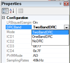
    By default, the GUI is configured with only one AGL, in order to use the AGLs as crossover, you need to set the DRC Band parameter in the main properties window as "TwoBandDRC" (sorry for the name confusion, the AGL is named DRC in the GUI):

    Then, the crossover frequency can be changed when selecting the "Two Band DRC Crossover" Block:

    By the way, I would like to mention that this device is quite old, we have newer amplifiers which have better performance, lower BOM count and easier end-system integration, like the TAS5753MD, TAS5751M or TAS5733L. 

    Best Regards,

      -Diego Meléndez López
       Audio Applications Engineer

  • Dear Diego,

    Thank you. We will test it out.

    Regards,
    CK
  • Dear Diego,

    We managed to enable the LOWBAND and HIGHBAND to operate in series with the crossover at 200Hz.
    However, we notice that the AGL did not work for frequency around 200Hz. That means, if there is 200Hz signal exceeded AGL limit, it is not suppressed by the AGL.
    What are the settings we need to do to ensure 200Hz signal is not missed by AGL?

    Regards,
    CK
  • Hi, CK,

    This is a strange behavior. I would recommend you to analyze the output of each AGL turned off independently on the frequency domain to verify that the filters are working correctly. Then you can check the behavior of each AGL and verify if they are working as expected. Can you please share the register configuration or GUI settings used so I can test it in my EVM?

    Best Regards,

      -Diego Meléndez López
       Audio Applications Engineer

  • Dear Diego,

    Pease find attached the DRC configuration.

    USB3.0 DSP Two Band CFG_20160730A.cfg

    Regards,

    CK

  • Dear Diego,

    Did you manage to reproduce the sympton at crossover frequency?

    Regards,

    CK

  • Hi, CK, 

    Sorry for the late response, I reviewed your configuration file and I noticed that the Equalizers for the Right Channel AGL are not configured. So, you need to add the following lines to your code in order to get the biquads configured:

    X5C 00 7D A6 E3 0F 04 B2 39 00 7D A6 E3 00 FB 42 C1 0F 84 A7 33
    X5D 00 7D A6 E3 0F 04 B2 39 00 7D A6 E3 00 FB 42 C1 0F 84 A7 33
    X5E 00 00 05 83 00 00 0B 06 00 00 05 83 00 FB 42 C1 0F 84 A7 33
    X5F 00 00 05 83 00 00 0B 06 00 00 05 83 00 FB 42 C1 0F 84 A7 33

    Is your issue present in both channels? as the biquads of Right channel are not configured, the AGL may not be working correctly in this channel. 

    Best Regards,

      -Diego Meléndez López
       Audio Applications Engineer

  • Hi Diego,

    How is your check on my configurations?

    Regards,

    CK

  • Dear Diego,

    We saw it in Left Channel.

    Regards,
    CK
  • Hi, CK,

    I was testing this in the EVM, and I verified that the routing is correct. However, your timing parameters were causing me some trouble. Can you please provide the timing parameters of the AGL you are planning to use?. About your issue, the signal in 200Hz is properly being limited by the corresponding AGL in my test so I am unable to replicate your issue. Could you please provide more information on the test you did to find the problem?

    Thanks. 

    Best Regards,

      -Diego Meléndez López
       Audio Applications Engineer

  • Dear Diego,

    We ganged the Left and Right channel, so supposingly both channel will have same setting.

    My mistake. We configured the AGLs in Parallel mode.
    With CrossOver at 200Hz.
    We found the Parallel configuration cannot limit 200Hz. The distortion will just go up to >8%. We have tried other crossover frequencies, and confirmed that the issue follow the crossover frequencies.
    The attack is in few ms, and the release is 1.3sec (as this help to limit some noise on our system).

    Can you send us the configuration that is able to limit 200Hz with Crossover at 200Hz?

    Regards,
    CK
  • Hi, CK,

    Thanks for the feedback, The ganging does not affect the Crossover biquads, so you need to configure the ones of the right channel manually as the GUI is not configuring them. I expect to provide the configuration I used by tomorrow CDT.

    Best Regards,

      -Diego Meléndez López
       Audio Applications Engineer

  • Dear Diego,

    Thank you. Looking forward for your configuration.

    Regards,
    CK
  • Dear Diego,

    How is your recommendated configuration for parallel AGLs?

    Regards,
    CK
  • Hi, CK, 

    Sorry for the delay, I was quite busy lately. It makes sense the crossover frequency is not fully limited if the AGLs are configured parallel. This is because in series, the High Band AGL limits any signal over the threshold level, including the output of the Low Band AGL. For the case of the Parallel AGL, both AGLs are summed in the output, causing an overlap of "limited signal" over the crossover region:

    In order to get the amplifier configured with Series AGL at 200Hz Crossover frequency, please refer to the attached script.

    Best Regards,

      -Diego Meléndez López
       Audio Applications Engineer

    2BandAGL_Series_CK.cfg

  • Dear Diego,

    We had successfully configured AGLs in series mode.
    We need AGLs in parallel mode, as we need higher AGL for LOWER BAND.
    We tried to configure AGLs in parallel mode, but we are getting no limiter at crossover frequency, not just double. Any solution for this?

    Regards,
    CK
  • Hi, CK,

    Thanks for the clarification, I modified the script to use a parallel AGL configuration (attached). I will try this in my EVM and will get back to you with any update, probably by tomorrow.

    Best Regards,

      -Diego Meléndez López
       Audio Applications Engineer

    2BandAGL_Paralell_CK.cfg

  • Dear Diego,

    Any update on your test with EVM?

    Regards,
    CK
  • Dear Diego,

    Any update on your test with EVM?

    Regards,
    CK
  • Dear Diego,

    If this is an known issue for TAS5717, please let us know. There is no meaning for me to waiting for known issue to be resolved with settings.

    Regards,
    CK
  • Hi, CK, 

    Sorry for the delay, I was trying to find time to check this. With Parallel AGL, the output response won't be flat if the volume of the amplifier is >0dB. this is because the mixing of both AGLs is made in the output mixer. When the volume of the amplifier is above 0dB, the AGLs can limit the signal level, but as the filtered frequencies (>200Hz for the Low Band AGL, <200Hz for the High Band AGL) are boosted by the volume increase, the unfiltered frequencies of both AGLs will be summed, causing the peak in the crossover frequency to appear. This behavior is expected in Parallel AGL configuration. 

    Best Regards,

      -Diego Meléndez López
       Audio Applications Engineer

  • Dear Diego,

    Does it mean if the volume is at 0dB, the peak will not happen?

    Regards,
    CK