This thread has been locked.

If you have a related question, please click the "Ask a related question" button in the top right corner. The newly created question will be automatically linked to this question.

TPA3251 slave mode PWM input clock issue

Other Parts Discussed in Thread: TPA3251

Hi team,

Our customer  have two questions about TPA3251

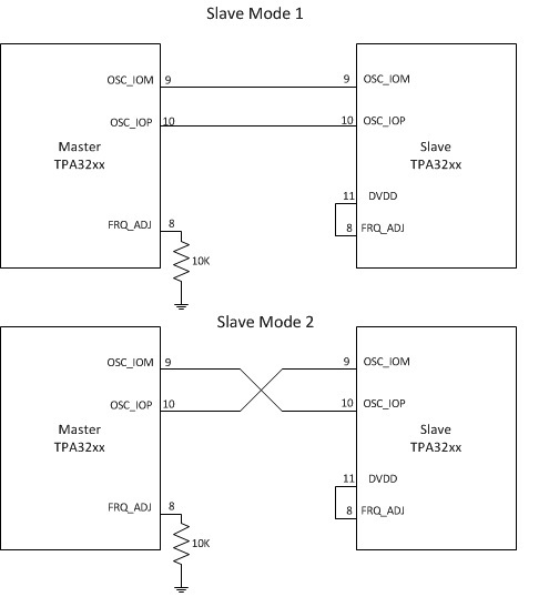
  1. How to sync two TPA3251?  If using TPA3251 as a slave device, pull up pin9/10 to VDD and input clock as a PWM clock? Could  you send me a simple current connection block diagram to me?
  2. In our EVM user’s guide description ,it is the AD mode, But from the LC filter connection of EVM SCH, It is BD mode,Why?

  • Hi Bing,

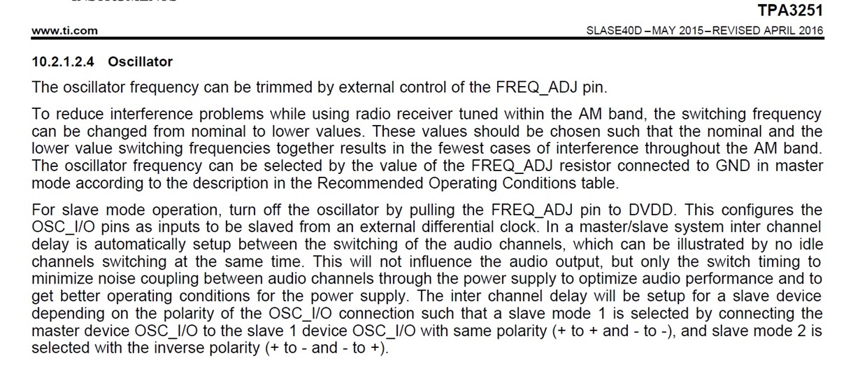
    1. To sync devices one must be configured as master and the other as a slave. To configure the slave device pull FREQ_ADJ (pin 8) to DVDD. Then connect the OSC_IOM and OSC_IOP pins. The phase of the synchronization between devices can be changed by swapping the connections of the OSC pins.

    See diagram:

    From the datasheet:

    2. We use a BD cap configuration on the EVM because the EVM must also support single ended output. Therefore all outputs must have and inductor and capacitor for SE output. This configuration also gave good performance in BTL. An AD filter configuration can be used however some testing may be required to meet same performance.

    We just launched a new LC Filer tool: http://www.ti.com/tool/lcfilter-calc-tool  

    Best Regards,

    Matt