This thread has been locked.

If you have a related question, please click the "Ask a related question" button in the top right corner. The newly created question will be automatically linked to this question.

TAS5624A PBTL + BTL Combination

Other Parts Discussed in Thread: TAS5624A, TAS5614LA

Hello,

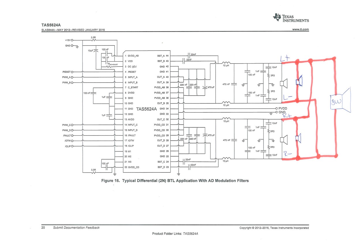
I am building a prototype car amplifier. Default car has 4ch input for speakers. However there will be a subwoofer too. What I would like to is something like as I attached. I want to drive FL-FR, RL-RR + SW. Front and Rear will be the same stereo line. How much power can I have in this configuration(? Is it same? Are there any other requirements? Should I put a low pass filter?

Regards,

  • Hi, Mehmet,

    Welcome to E2E, Thanks for your interest in our products!.

    I have asked my colleagues to help you with your question, they will contact you as soon as possible. 

    Best Regards,

      -Diego Meléndez López
       Audio Applications Engineer

  • Hello,

    The main consideration here is amplifier load impedance. The TAS5624A is rated for 4ohm minimum load in BTL. Therefore, the combined impedance across each output (L+ L-) and (R+ R-) should be 4ohms or greater.

    In 4ohms the amplifier can deliver 150W.

    With this configuration there is no control over the subwoofer output and frequency response. Therefore matching the SPL of the subwoofer to the L & R channels will be difficult. Our recommendation is to use a separate amplifier for the subwoofer and control volume and frequency response in the PWM modulator before the power amplifier.

    Best Regards,

    Matt

  • Hello,

    Thank you for your reply. I would like to use single amplifier due to pcb size restiriction. If I give up from amplifier option can I drive 4ch of differential speakers? Like in the SE configuration but I want to have differential output.

    Thanks

  • Hello,

    You connection diagram above should work, however we have not tried this configuration.

    I recommend testing this with the TAS5624A EVM www.ti.com/.../TAS5624ADDVEVM first to verify the configuration before designing your own PCB.

    Speaker selection is important as to not to violate the amplifiers 4ohm minimum impedance rating in BTL.

    Best Regards,
    Matt
  • Hello,

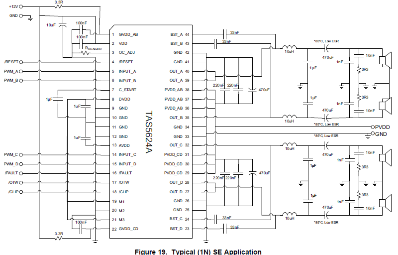
    Actually I am working based on the reference design in the evolution module document. However the main problem for me I want to use tas5624a or tas5614la and control the 4 channels separately with differential outputs. The one first I sent I think not a reliable configuration, I would like to have this kind of configuration (4 speakers driven separately) with differential output:

  • Hello,

    The configuration shown above is referred to Singe Ended (SE) mode. Here one side of the speakers are connected to ground so they are not driven differentially. In this mode each speaker is driven by one 1/2 bridge rather than a full bridge. DC blacking caps on the output are required as shown (470uF) since each output is biased to 1/2*PVDD.

    We have a new applications note that discusses the Class-D configurations in section 1: http://www.ti.com/lit/an/slaa701/slaa701.pdf

    In the 4x SE configuration, all 4 channels can be driven with independent audio signals. Please review the datasheet for performance in SE mode.  

    Best Regards,

    Matt