This thread has been locked.

If you have a related question, please click the "Ask a related question" button in the top right corner. The newly created question will be automatically linked to this question.

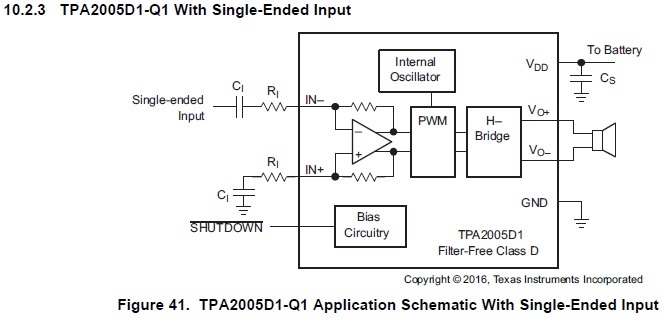
TPA2005D1-Q1: Single-Ended Input with 88kHz PWM from µC

Part Number: TPA2005D1-Q1

Hello,

my customer wants to use TPA2005D1-Q1 with the single-ended input configuration in order to replace a discrete H-Bridge stage.

The input signal is a PWM (88 KHz) from µC output. Is the IC expected to work with this kind of input signal, or should this IC be just used with a signal generator (sine wave)?


R = 150k and C= 53nF as filter on pin 3 and pin 4 is connected to ground. But the signal is attenuated at the input pin.


Connecting pin 4 with C = 53nF and R = 150k to GND instead of connecting it there directly was done initially and there was just noise on the output.


Are the capacitor values wrong? In the EVM documentation it is in the range of µFs.


SHUTDOWN pin is connected to pin 6 i.e VDD i.e the IC is always enabled.


Is the frequency out of range for this IC?


What is the maximum frequency that it can generate on it’s outputs?


Thanks for your advice!

Martin

  • The input capacitor serves two purposes here.  It provides a HPF that will block DC, but it also allows the device to bias the input common mode correctly.  The 53 nF capacitance matches what is shown in the datasheet to set the corner frequency of this filter to 20 Hz.  However, with the second input grounded, we prevent the device from properly biasing the input.  Pin 3 will bias to Vdd/2, while Pin 4 remains grounded.  This will generate a large DC offset at the inputs.    This will also limit the useful input range of the device.

    When the capacitor was used on pin 4 was the noise the result of the 88 KHz input, or was it idle channel noise?

    Little is shown in the datasheet to indicate the input frequency range.  All plots stop at 20 KHz, and so I cannot tell what result will occur with an input on the order of 88 KHz.  I do see that CMR starts to decline just before 20 KHz, and would expect that this device was intended for purely analog audio input below 20 KHz.  

  • It was idle channel noise. However even with input signal, the output was not as intended.

    Used signal is in the audio range with frequencies 250Hz, 500Hz, 1KHz, 2KHz, 4KHz and 8KHz. However there is a high frequency PWM within these.

    We will check again with typical audio signal output from a generator and use the EVM to test with the speaker.
  • Thanks for the input.  Please let us what you observe when using the EVM.