This thread has been locked.

If you have a related question, please click the "Ask a related question" button in the top right corner. The newly created question will be automatically linked to this question.

LM4670: low resistor issue reported in pins VO1/2 of LM4670.

Part Number: LM4670

customer reported low resistor issue in pins VO1/2 of LM4670. it looks like EOS issue. is there any comments for for VO1/2 EOS improve?

  • Hi Peter,

    I need more details about the application in order to provide you better support. Do you know the resistance value that they are getting?

    Best Regards
    José Luis Figueroa
    Audio Applications Engineer
  • Hi Jose,

    This is Jason and Peter is our TI local FAE of LM4670 EOS issue. I would describe my LM4670 failure issue as following.

    Since we meet the failure cases frequently in out production line recently, I may need your help to check this issue.

    Symptom:

    SPK is not functional and LM4670 VO1 (pin5) pin shorted to GND(pin6).

    Failure Condition:

    both in production line and returned from field

    Failure Rate:

    16/4230 (2 from field and 14 from production line)

    TI FA analysis of first 2 returned defected samples:

    LM4670 EOS damage. (see attached FA report from TI)

    SPK spec:

    3W/4ohm

    Questions:

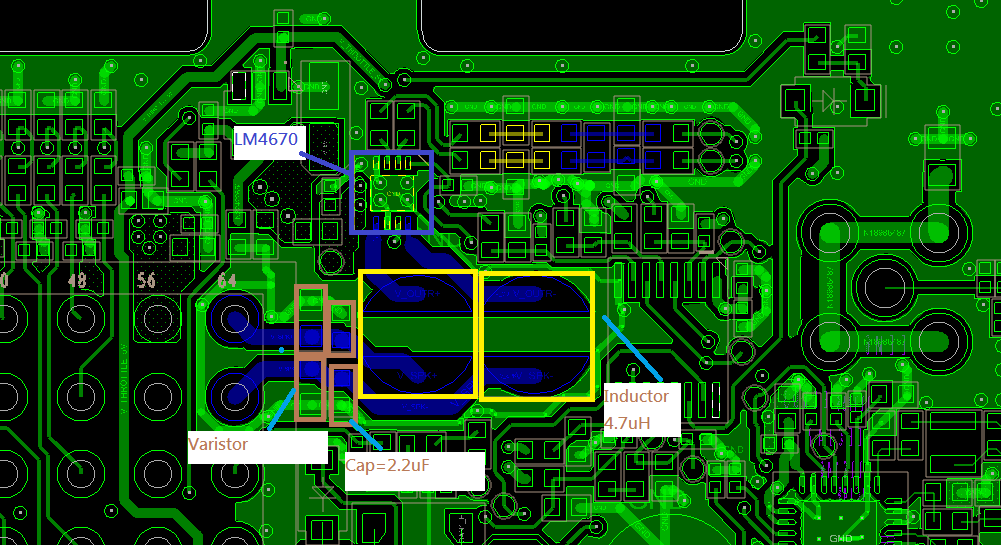
    1. I have attached the schematic and layout of my design. Could you help check if any risk of damaging the VO1 or VO2 to short to GND?

    2. Has TI been reported similar issue from your other customers?

    3. How to avoid the EOS damage of VO1/2?

    4. What is the maximum pin voltage endurance of VO1/2 output pins?? the spec seems not to annotate it. I need this data to review if any risks.

    5. The FA states the failure is caused by high voltage EOS of VO1 pin, but we can not figure out where the high voltage energy comes from between the defected VO1 and Inductor (EEL21). I don't think the high voltage is from connector side because the varistors (Located after the inductor EEL21 and closed to connector) is NOT damaged. If the high voltage is from connector side, the varistor should be damaged also.  I may need your comment on this.

    Thanks for your great help.

    QEM-CCR-1706-01197.pdf

    0638.SCHEMATIC1 _ 04-MB_SPK.pdf

  • Hello Jason,

    1) Peter provided me some graphs of the signal measured and I noticed that the PWM output signal is getting large peaks. I think that this could be a decoupling issue and would be causing the output noise. I noticed that you are using a via on Vdd pin, but it is recommended to place all the decoupling capacitors as close as possible the device and on the same layer. This condition could be the problem.
    2) No, we haven't been.
    3) As you are doing it using varistors.
    4) Do you mean ESD ratings? if so, you can find them on the Absolute Maximum Ratings on the datasheet.
    5) Another possible cause of getting peaks at PWM output signal could be a bad selection of the output inductors. Perhaps this could be generating EOS damage. You should make sure that inductor saturation current rating is greater than the maximum operation peak current.

    Best Regards
    José Luis Figueroa
    Applications Engineer
  • Hi Jose,
    Thanks for your quick reply.
    For item5, I would like to double confirm my calculation of the operation peak current is correct.
    Vout=5V
    SPK Rdc=4ohm+/-15% -> 3.4ohm < Rdc< 4.6ohm
    Imax=5V/3.4ohm=1.47A (If the Rdc is bigger, the peak current is smaller??)

    As the schematic inductor characteristic, ISat of the inductor is 1.7A should be enough.

    Is my calculation correct?

    Thanks
  • Hi Jason,

    You should take into account the high peak output current instead of nominal value. You could disconnect the output filter to check the device's output operation in order to determinate if the problem is the filter.

    Best Regards
    José Luis Figueroa
    Applications Engineer
  • Hi José ,
    IF we set LM4670 VDD=5V Rin=240K (Gain=1.26x), Vin PWM =3.3V. And Speaker Impedance = 4ohm ±15%.(3.4~4.6ohm).
    Base on this condition , Will LM4670 be overload ? We want to know the max output current that LM4670 in VDD=5V.
  • Hi Simon,

    I don't think that under these conditions the device is overloaded. But the PWM input signal is not a normal condition, this device is designed to work with sine input signal.

    Best Regards
    José Luis Figueroa
    Applications Engineer
  • Hi José,

    We input the sine signal into the LM4670 SPK AMP. (CPU outputs the PWM and we use C/R to convert the PWM into sinewave and inputs to SPK AMP)

    With your previous reply, we have measure the VO1/2 waveform with and without the output filter inductors.

    I found the output overshoot can be as high as 7.2V with output filter INDUCTOR and 6.4V without output filter INDUCTOR .

    Could you help check the max voltage overshoot tolerance of LM4670 VO1/2 pins?  I can not find any other possibility which can have EOS damage of the VO1/2.

    Thanks

  • Hi Jose,

    Could you help clarify if LM4670 is with output short protection? I did an experiment to short VO1 and VO2 when playing sound, the same failure symptom  (VO2 short to GND) can be reproduced and the chip is damaged.

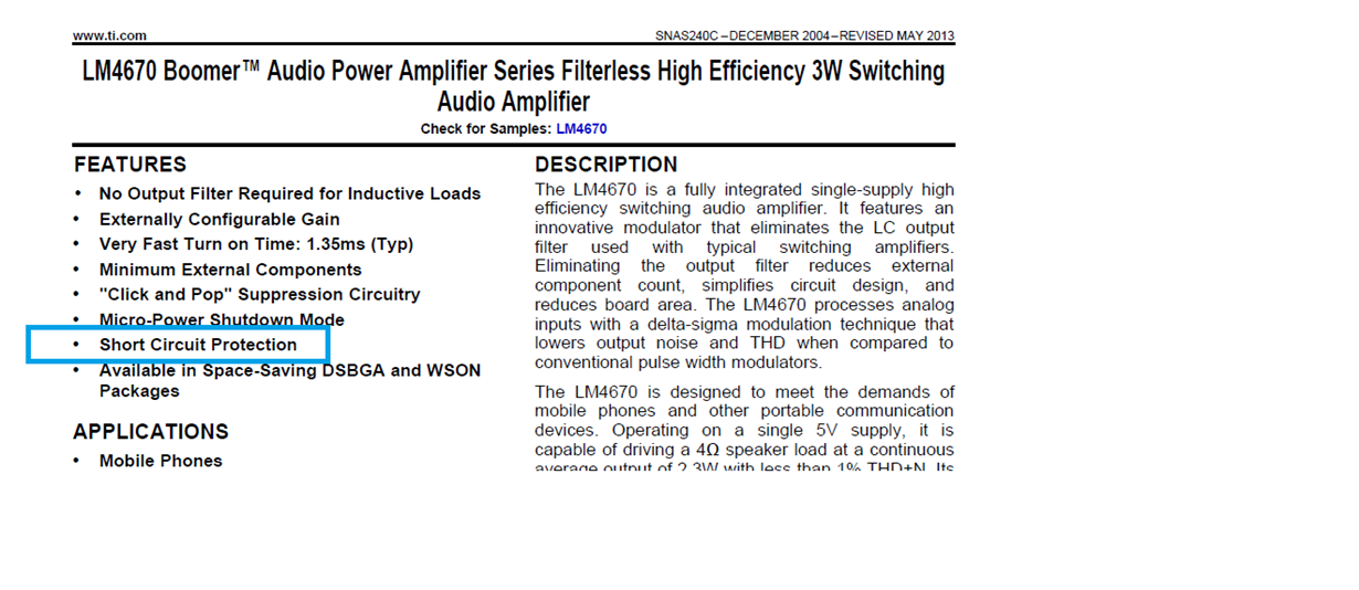
    I checked the LM4670 datasheet and see it is with short circuit protection,  but it seems not with my experiment.

    Please help clarify.

    Thanks

    Jason

  • Hello Jason,

    I am not sure about maximum voltage overshoot tolerance, but the device should not exceed the Absolute Maximum Ratings. In this case, it would be 6Vrms.
    Unfortunately, I don't have any detailed information as short circuit protection works on this part because it is a very old device and the people who worked with these parts aren't longer on TI. Besides, this device doesn't have an EVM available to perform this test.
    Have you placed the decoupling capacitor on the same layer? If not, I think that is producing the large peaks on PWM output signal and this is possibly causing the ESD problems.

    Best Regards
    José Luis Figueroa
    Applications Engineer
  • Hi Jose,

    I am thinking about the necessity of output LC filter or just using the ferrite bead instead.

    My application is connecting the SPK AMP to SPEAK by a 1.5M wire harness. I may need your advice about the risk if I remove the  LC filter and use ferrite bead instead.

    Thanks

  • Jason,

    The change should not generate any problem. Keep in mind a ferrite bead filter is used to reduce very high-frequency interference and LC filter is used for very stringent EMI requirements.
    You can refer the Output Filter Desing Considerations to find further information.

    Best Regards
    José Luis Figueroa
    Applications Engineer