This thread has been locked.

If you have a related question, please click the "Ask a related question" button in the top right corner. The newly created question will be automatically linked to this question.

TAs5760M: Soft Clip of TAS5760M

Part Number: TAS5760M
Other Parts Discussed in Thread: TPA3116D2, , TPA3118D2, TPA3118D2EVM

Dear Sirs,

My customer asked us about Soft Clip of TAS5760M.

He used TAS5760M & TPA3116D2.

He compared and confirmed the items of Soft Clipper and Plimit in each data sheet.
So the values of Table 4. Soft Clipper Example and Table 3. Power Limit Example were exactly the same.
However, I think that it does not become the same if it is made from measurement formulas.
So question 1
Are both measurement conditions (setting conditions) the same?
Please tell me the conditions of each table.
Also TPA 3116 D 2 has Plimt's characteristic figure on the data sheet but there is no TAS 5760 M soft clip figure.
Do you have it?

Question 2
On the TAS 5760 M data sheet, in describing the SoftClipper function,
There is VP = 4 × VSFT_CLIP.
Is this the clip voltage at no load?
I confirmed with EVM, the Vsft_Clip voltage did not change.
Does the voltage change with or without load?

Best Regards,

Y.Hasebe

  • Hello! Andy can help clarify your questions. Thanks, Jeff
  • Hi Yoshiki,

    See my comments below:
    Q1: Are both measurement conditions (setting conditions) the same?
    Andy : TAS5760M and TPA3116D2 are different types of Class D amplifiers so the test conditions are different. The test conditions for the Power Limit Examples are already mentioned below Table 3 ("PLIMIT measurements taken with EVM gain set to 26dB and input voltage set to 1Vrms"). In addition, the data in Table 3 are real measurement data and should be repeatable under the same test conditions.

    The reason for these two same examples tables is that the design idea for SFT_CLIP and PLIMIT pins are identical, which is to clip the output voltage level below the supply rail. You can tell that from the similar descriptions about these two pins in the their datasheets.

    Q2: Also TPA 3116 D 2 has Plimt's characteristic figure on the data sheet but there is no TAS 5760 M soft clip figure. Do you have it?
    Andy: No, I have not yet found that type of plot for TAS5760M.

    Q3: Does the voltage change with or without load?
    Andy : The voltage at the SFT_CLIP pin is a reference voltage for internal circuit and should not change with load.

    Andy
  • Hello Andy-san,

    Thank you for your quick reply.

    I have additional some question.

    Q1.

    Andy : TAS5760M and TPA3116D2 are different types of Class D amplifiers so the test conditions are different. The test conditions for the Power Limit Examples are already mentioned below Table 3 ("PLIMIT measurements taken with EVM gain set to 26dB and input voltage set to 1Vrms"). In addition, the data in Table 3 are real measurement data and should be repeatable under the same test conditions. 

    ⇒I understand dfferent type AMP TAS5760M and TPA3116D2. Also I think so that test condition.                                                                                                                                                                                                However, if the data in Table 3 is the measured value, it is not clear that Table 4 of TAS 5760 M has exactly the same value as Table 3 of TPA3116D2.                                                                                                        Please tell me the measured value of TAS5760M.

    For reference, when I measure with TAS5760MEVM, it becomes the following value.
    Condition: GUI: Used PPC 1.16

                              PVCC=24V       RL=8Ω

    Vsft (V)     Vout (Vp - p)    Pout(Unclipped)Vrms    Pout (W)                      

       7                             46.8                               16.5                               34                                                                                                                                                                                                                                       3.3                           27.6                                9.75                             11.9                                                                                                                                                                                                                                    2.25                          17.6                                6.2                                4.8

    There is a difference between this value and the data sheet value.

    Q2:

    Andy: No, I have not yet found that type of plot for TAS5760M.

    ⇒Could you please give us if data is found?

    Q3:

    Andy : The voltage at the SFT_CLIP pin is a reference voltage for internal circuit and should not change with load.

    ⇒I understand your comments.


    Best Regards,

    Y.Hasebe

  • Hi Yoshiki,

    Could you send your TAS5760MEVM measurement results again? I cannot read them now. To make it easy, you can just upload a screenshot. Thanks.


    Andy
  • Hello Andy-san,

    I'm sorry .

    TAS5760MEVM measurement results shows as below.

    Best Regards,

    Y.Hasebe

  • Hello Andy-san,

    Could you see the measurement results?


    Best Regards,
    Y.Hasebe
  • Hi Yoshiki,

    As you may see, the title of Table 4 is Soft Clipper Example, which means it is an example just for reference.  Actually the Output Voltage [Vrms] in that table is not the unclipped RMS voltage in your measurement data. 

    Blow is how to replicate the similar results as the Table 4.

    Step 1:  Set SFT_CLIP pin voltage to GVDD (7.00V) and adjust the digital input to TAS5760EVM until the output RMS voltage is close to 17.90Vrms.

    Step 2: Change the SFT_CLIP pin voltage to 3.3V and then to 2.25V.  Measure the output RMS voltage and you will see similar results as the Table 4 shows. 

    Andy

  • Hello Andy-san,

    I understand your comments.
    I will try it tomorrow.
    (Because I don't have EVM today.)

    By the way , i have one more question.
    With SoftClipper (PLIMIT) setting condition on TAS5760M and TPA3116D2,
    What is the reason of the difference in the unclipped output value?

    Best Regards,
    Y.Hasebe
  • Hello Andy-san,

    I have checked your suggesting confirmation.

    The result as follows.

    As you said, it was a close result.

    Thank you for your quickly and kindly reply.

    I will answer to my customer it.

    So what about the additional questions of yesterday?

    With SoftClipper (PLIMIT) setting condition on TAS5760M and TPA3116D2,
    What is the reason of the difference in the unclipped output value?

    Best Regards,

    Y.Hasebe

  • Hi Yoshiki,

    What do you mean by "the difference in the unclipped output value"?  Could you explain to me with more details or show me some data?

    Andy

  • Hello Andy -san,

    This means the output voltage just before clipping or the output voltage that starts clipping.

    It is the data before you get advice on measurement conditions from you.

    Please to see below.

    TAS5760MD DATA

    TPA3118D2 DATA

    It is the data before you get advice on measurement conditions from you.

    Compared to the data of TPA3118D2 under the same condition, it was 3 V different.

    According to your comments

    First of all, it is necessary to set the maximum value of 17.9 V of Vsft as a prerequisite, and the output voltage when changing Vsft to 3.3 V, 2.25 V in that setting state was indicated in the table.

    I have also measured and understood this.

    But the reason for asking additional questions is because if you have information on the point where distortion begins, I would like you to tell me.

    (Because the initial point of distortion is also important in the design)

    Best Regards,

    Y.Hasebe

  • Hi Yoshiki,

    Allow me to double check your data and then get back to you.

    One question, what kind of criteria did you use to tell whether the output is clipping or not when you took these measurement data? Did you use TI EVMs to get these results?

    Andy
  • Hello Andy-san,

    Thank you for your reply.

    Measurement conditions are as follows.

    For measurement, we used TAS5760MDEVM and TPA3118D2EVM.

    TAS5760MDEVM:
    PVCC: 24V
    Input: OPTICAL, 1 kHz, -12 dB
    GUI: PPC 1.16,
    AnalogGain: 24 dB
    DigitalGain: The input level can be changed by Volume Control.
    Load: 8 Ω

    TPA3118D2EVM:
    PVCC: 24V
    Input: Analog, 1 kHz Input variable up to Max 2 Vrms (0 dBFS Max for AudioInterface usage)

    I measured the output at which distortion starts under the above conditions.

    Best Regards,

    Y.Hasebe

  • Hi Yoshiki,

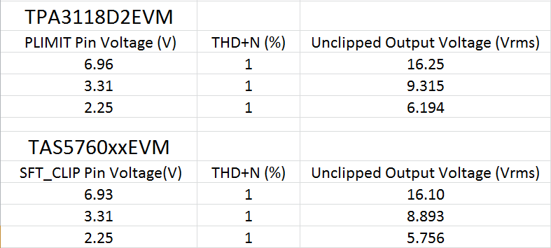
    Below are the data I just took this afternoon. In my test the unclipped output voltage is defined as the max voltage when THD+N is <= 1%.  The unclipped output voltage of these two devices are similar to each other based on my results.

    Test conditions:

    PVDD = 24V

    Load = 8 ohm

    Andy

  • Hello Andy-san,

    Thank you for your kindly reply.
    I understood your result.

    My measurement condition may have been wrong.
    I will check again.

    Best Regards,
    Y.hasebe