This thread has been locked.

If you have a related question, please click the "Ask a related question" button in the top right corner. The newly created question will be automatically linked to this question.

TPA3128D2: THD Performance in Hybrid/1SPW vs. BD modulation when using single-ended input (compared to fully differential drive)

Part Number: TPA3128D2
Other Parts Discussed in Thread: STRIKE, TPA3118D2

Dear TI,

we came across some performance issues while testing 2 new amplifiers based on TPA3128D2 when running in a single-ended (pseudo-differential) input configuration as this is pretty much standard for consumers.

The board is configured as follows:

PVCC: 24V isolated linear bench power supply 150W
Gain: 26dB
Input-Config: Pseudo-Differential
fSW: 600kHz
Modulation: 1SPW aka "Hybrid"
Load: 5R/10R resistive
Config: 2xBTL
Measurement setup: EMU0202 with -30dB differential attentuator
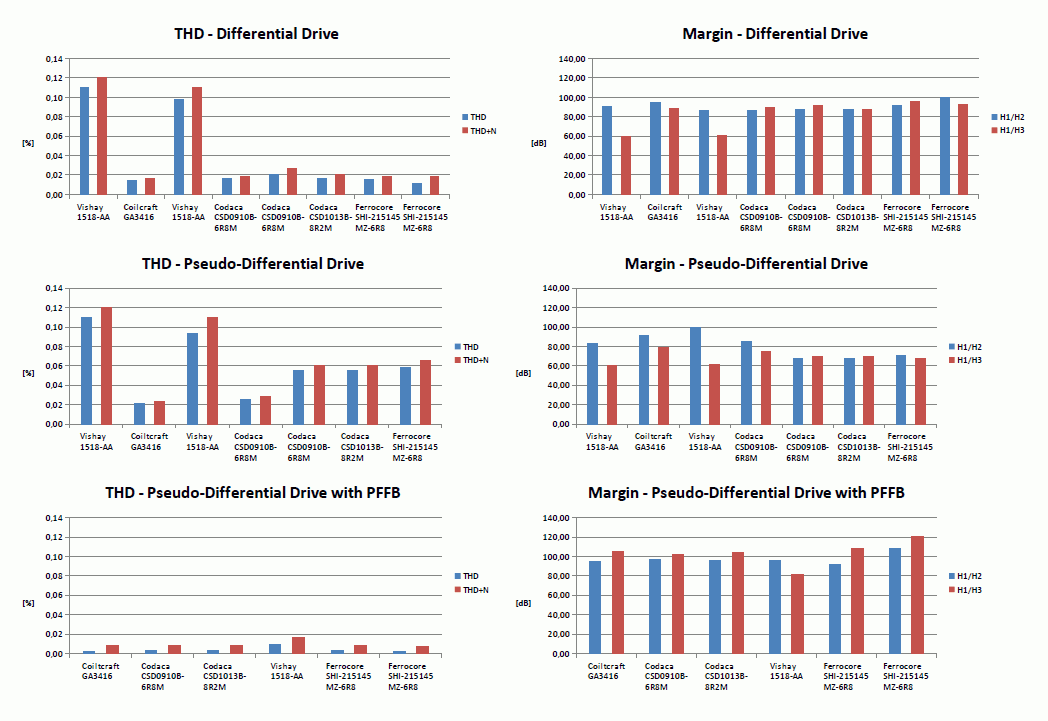
THD Plot:

The modulation changes between 1.5Vrms and 4Vrms this can clearly be seen for 10R load. Is this to give better specs in the datasheet?

Changing modulation to BD is a game changer but still not the optimum.

Out of curiosity, we set up a different implementation (completely different board layout with high-power inductors "Ferrocore SHI-215145 MZ-6R8") which shows the following plot:

This measurement was done some 500km away from my lab, results are similar.

When we change the input configuration from pseudo-differential to fully-differential, the plot is pretty much spot on the datasheet specs:

Why does TI not mention this "poor" performance in pseudo-differential mode in the datasheet? Isn't it like 90% of the consumer products do only single-ended input configurations? Pretty disappointing.

Results from the testbench:

input config fully differential pseudo-differential pseudo-differential
output 1.harmonic (H1) dBV 20.64 20 10
output 2.harmonic (H2) dBV -71.5 -47 -77
output 3.harmonic (H3) dBV

-75

-44 -69
H1/H2 dbV

92.14

67 87
H1/H3 dbV

95.64

64 79

Conclusion:

1SPW/Hybrid is a nice powersaver, but does pretty poor THD performance when not driven fully differential. It would be nice if TI could make this more clear in the datasheet instead of "hiding" important informations. Is there any performance data available from the TI department for this chip when using pseudo-differential mode?

Thanks in advance!

Best regards,

Christian Weidner
www.360customs.de

  • Hello Christian! Thanks for your feedback and we do appreciate you position. We had to strike a balance during the definition / design process for this device in parallel to to some key target audio market drivers that had some particular needs. So, as you can imagine this drives some give and take when it comes to feature implementation. We opted to focus on implementing our BD/1SPW Hybrid modulation scheme approach to extend overall battery life, while also focusing on performance in a fully differential configuration, hence this where much of the datasheet positioning came from. Our intent was not skip over anything, but to focus on the target. I will work with the team to make such product positioning as clear as possible going forward. Thanks for your interest and support. Thanks, Jeff
  • Hi Jeff,

    thanks for the reply and openess. Please see my word as constructive criticism. :-)

    May you answer this question please?

    > Is there any performance data available from the TI department for this chip when using pseudo-differential mode?

    Best regards,

    Christian
    www.360customs.de
  • Hello Christian! No problem... your feedback is very useful to us. In particular because 360customs turns out some outstanding designs and helps to further the audio market. I will look to my Char team to see if we have any pseudo-differential data that may be useful and then get back to you. Thanks, Jeff
  • Hi Christian,

    THD performance should be close between single-ended input mode and differential input mode. And it should be also close between BD mode and 1SPW mode. The following chart shows the THD performance with single-ended input mode on TPA3128D2 EVM, the green one is for 1SPW mode and the yellow one is for BD mode. PVCC=24V, Load=8Ohm. We can see that the performance is very close between them. 

    THe following chart is shown for differential input mode. The performance for 1SPW mode (green one) is also very close to BD mode(yellow one).

    And if you compare single-ended mode to differential mode, the performance is also very close, maybe 0.01~0.02% difference.

    THD measurement is a very sensitive test, please make sure the good GNDing between your board and the instrument. Please also refer to our TPA3128D2 EVM design.   

    Best regards,

    Shawn Zheng

  • Hi Shawn,

    thanks for the plot. Would you mind to tell us the integration parameters and what filters where used? The first plot is quite similar to ours, switching the modulation sheme is between 1.3W-5W but much more damped on your plot. Is this a pure resistive load?

    > THD measurement is a very sensitive test, please make sure the good GNDing between your board and the instrument.

    Well, we did the measurement on 2 different labs miles away from each other on two totally different board layouts with different input/output filters and the result is shown in the first post for pseudo-differential input.

    Best regards,

    Christian

  • Hi all,

    i'll come back with new insights regarding this phenomenon. There might be some side effects/interaction with the inductors used which boost the THD rise when modulation switching occurs.

    Best regards,

    Christian

  • Thanks Christian and Shawn!
  • Good morning all,

    i want to give a short update/provisional result.

    When scaling our plot results to fit the ones TI provide, the following can be shown:

    With the shown EVM performance, the difference between fully/pseudo-differential drive is hardly seen due to higher THD compared to our implementations. At the lower end this might be caused by higher system noise either from the board/psu or the AP. From 1W onwards THD performance is most commonly affected by inductor current saturation effects or dL/dI.

    We'll have the small PCBs shown in the first post crossmeasured in another lab to confirm our findings.

    I will keep you updated, best regards,

    Christian

    Edit: May someone from TI please provide the APs integration/transient time constants? These really matter when measuring Hybrid mode due to common mode output voltage stepping.

  • Hi Christian,
    Thank you very much for your update. I fully agree with you that the inductors dominate the THD performance with higher output power(usually more than 1W). About the transient time constants setting on AP, it does affects the THD performance. But for my experiment result, it doesn't affect much. I tried with different setting on AP, and the result is very similar.
    Best regards,
    Shawn Zheng
  • Hi Shawn,

    would you mind to tell us the numbers?

    Best regards,

    Christian

  • Hi Christian,

    We measured the THD performance with different detector reading rate(also called integration time), from 4/sec~128/sec.The test fails in both BD and 1SPW mode for too fast rate setting, but the result is very similar for the stable rate settings. For those settings, the THD difference is less than 0.01%.

    Best regards,

    Shawn Zheng

  • Hi all,

    i want to round this topic up, so here are the latest results from our measurements in the other lab.

    Differential vs. Pseudo-Differential in hybrid mode still shows different results:

    The switching in modulation is clearly be seen - increased in THD is due to the use of (Vishay) carbonyl inductors.

    Using different inductors (Codaca CSD0910B) will result in the following plot:

    Comparing both implementations in pure differential drive show that the pcb layout influence, in this case, is negligible.

    All the measurements in a table:

    And a comparison for THD and harmonics margin for differential/pseudo-differential and our pseudo-differential+PFFB approach. THD is measured at 20dBV output level into 5/10R at 1kHz and 400/600kHz.

    Pseudo-differential drive is about 15-20dB behind fully differential - except when using PFFB.

    All the data:

    TPA31xx_2017_09_07.zip

    Conclusion:

    Using the TPA3128 in hybrid modulation + pseudo-differential drive won't give the performance data noted in the data sheet.

    Best regards,

    Christian

  • Hi Christian,
    Thank you for the data. I'm impreseed by your resourceful work.
    When the output voltage is less than 0.1V, the measured THD+N is dominated by noise but not the linearity of the device, becasue the output power is very small in this case comparing to the noise. So usually we don't need to measeure THD for so low output power.
    According to our previous measurement on the TPA3128D2 EVM, the THD performance in Hybrid mode for differential and pseudo-differential input mode is close. The difference is acutally there, but 15~20dB is too much. Comparing the first and the second pictures, the difference looks not so much. Could you plesae let me know your input circuit design? For the single-ended input circuit, our recommendation is that just use 1uF capacitors for INN and INP, any component or device is not necessary between DAC output or GND and audio amplifier input. The 1uF capacitors should be high precision ones(e.g. X7R, COG). Make sure the matching on INN and INP routing perfect.
    As I mentioned before, differential input mode is always the first choice as soon as it's available. For most of the ananlog devices/circuits, differential mode circuit provides robust performance comparing to single-ended mode. For TPA3128D2, the THD peformance difference should be 0.0x% level.
    Best regards,
    Shawn Zheng
  • Hi Shawn,

    the 15-20dB difference is measured in Arta "spectrum analyzer" mode at 20dBV output level into 5R or 10R (20W/10W) at PVCC=24V as shown in the table i attached within the .zip file.

    f: 1kHz
    fs: 44k1/48k
    fft-bin: 16k
    avg: 20x linear

    The flipper board is equipped with: 2u2 16V X7R Soft-Term/Flex AEC-Q200 Murata GCJ21BR71C225KA13.

    Best regards,

    Christian

  • Hi Christian,
    Could you please try with 1uF or lower value capacitors? The larger input capacitors induce longer charging time, then longer time to set up the common voltage on the inputs.
    Best regards,
    Shawn Zheng
  • Hi Shawn,

    thanks for the reply. May i ask how the input coupling caps value is affecting the FFT measurement? The measurement is done with steady signal for the whole measurement, so common mode voltage is only set once and measurement starts after an initial delay to make sure everything is in steady state. Any change in inputs common mode is not parts of the measurement cycle.

    From the table data, the Voltwide boards without PFFB are 680nF, the ones with PFFB are 220nF.

    Best regards,

    Christian

  • Hi Christian,
    Yes, I agree with you that the FFT measurement is not affected if the common voltage is stable. But in Hybrid mode, there is a probablity that the common voltage changes with different output power. If a delay before each measurement is long enough that the common volatage is set up ready, there shouldn't be any problem. The performance for Hybrid mode and BD mode should be very close, because they are actually working in the same mechanism, as soon as the delay is long enough that the common voltage set-up is completed. For single-end input mode and differential input mode, the later has better performance of course. Please refer to our TPA3128D2 EVM design, all of my prvious data is based on this board. www.ti.com/.../slou457.pdf
    Best regards,
    Shawn Zheng
  • Dear Shawn,

    thanks for the reply. As we have shown here:

    the noise floor of your implementations seems to be lower than yours from the EVM, so the difference between pseudo-differential/differential is might/is most likely hidden below this line. Out of curiosity, would you mind to do an FFT measurement like ours and post the results for H1/H2/H3 in pseudo-differential/fully-differential configuration?

    Rload: 4-5R
    fSW: 400/600kHz
    Vout: 20dBV
    FFT: 16k Hanning Avg. x20

    Thank you very much.

    Best regards,

    Christian

  • Edit:

    I added another DUT to the comparison which isn't made by us but it widely available on the market. The difference between pseudo-differential/fully differential is also be seen with the older TPA3118.

    So this DUT is a TPA3118 in PBTL with NoName 10uH (undersized) inductors.

    What can be seen from the diagram? For small inductors which suffer from core saturation effects like the NoName and Vishay Carbonyl, the difference between PD (pseudo-differential) and FD (fully-differential) is dominant for H1/H2 (1kHz/2kHz). H1/H3 is bad for

    both, PD and FD. Using inductors from different material and bigger construction, the difference for PD and FD can also be seen for H1/H3.

    If everyone is fine with that we may come to an end. :-)
    Best regards,
    Christian

  • Hi Christian,
    Thank you for your great research on this. Again, I fully agree with you that FD mode has better performance than PD mode for both TPA3118D2 and TPA3128D2. And we always recommend customer to use FD mode as much as possible.
    If you don't have anygthing else to talk here, could you please close this quesion? Thank you.
    Best regards,
    Shawn Zheng
  • Hi Shawn,

    thanks for the reply and support, we really appreciate.

    Best regards,

    Christian