This thread has been locked.

If you have a related question, please click the "Ask a related question" button in the top right corner. The newly created question will be automatically linked to this question.

TAS5707EVM: no output from amp

Part Number: TAS5707EVM
Other Parts Discussed in Thread: TAS5707,

I am having trouble setting up my 5707EVM and producing an output with an analog input.  I have connected JP4 to ADC and shunted JP2 & JP3 near the RCA inputs.  I am not even sure if I am supposed to shunt JP2 & JP3 but think I saw it in another post.  The literature for setting this up is very unclear. 

I have setup the following:

1) Installed GDE & run application, go to 5707 tab

2) connect USB

3) power on 5V supply

4) power on 24V supply

5) connect target

6) unmute volume & set to 0dB

7) measure input voltage = 500mVrms

8) measure output voltage = 0Vrms

This passage from section 3 of 5707EVM User Guide is really confusing.  Any help would great.

  • Hi Michael,
    The first of all, could you please check whether the I2C communication is working? You are using an ananlog input signal, right? Please find the following post in wiki for theMC57xxPISA mother board configuration.
    e2e.ti.com/.../3529.mc57xpsia-board-input-configuration
    Did you check the output waveform on the output pin? The PWM output is switching or not?
    Please unmute the device output in GUI and make sure the 'ShuntDown' box is unchecked. Enlarge the master volume becasue the default value is very small.
    Best regards,
    Shawn Zheng
  • Can you describe how to check I2C communication and PWM output? I am a little new to the serial bus world...Thanks
  • I am able to get signal output now from the amp!  Very strange behavior though.  I was trying to use the I2C memory tool and it was not reliably reading the register values for master volume/mute (0x07).  The clock control register (0x00) was returning the appropriate value stated in 5707 datasheet but when I was toggling the mute button in the GUI it was not reading the value correctly.  When GUI was muted, the I2C memory tool would read back something other than FF which should be mute.  Then I would unmute in the GUI and memory tool shows the same value, 31 or something, sometimes after clicking Read twice the value would change and no output still observed at the amp output terminals.  Not sure exactly what The master volume was set to at that time but it was definitely 0dB or more.

    How do I convert the values read from I2C memory tool to dB?

    After disconnecting the target and reconnecting a few times and observing the flaky memory tool readings, I adjusted the volume slider from 0 to 8db or something and all of a sudden there was a signal at the output!.  Have you seen this before?  

    I might not have the best oscilloscope at the moment but am not too sure how to observe the I2C signals and PWM signals. To the best of my ability I was able to see a clock signal at the SCLK pin on the top of the J1 connector on the MC57xxPSIA board of about 2.5MHz.  I was not able to get any other reliable signals from the SCL or SDA pin.  Any guidance would be great.

    Thanks

    -Mike

  • Hi Mike,
    Congrutulation! When the inut signal amplitude is low, you need to enlarge the volume to achieve a larger output power. About the volume setting, please refer to the Table 12 in the TAS5707 datasheet. The PWM output is supposed to be 384kHz or 352kHz frequency square waveform. I believe you board is working well now.
    Best regards,
    Shawn Zheng
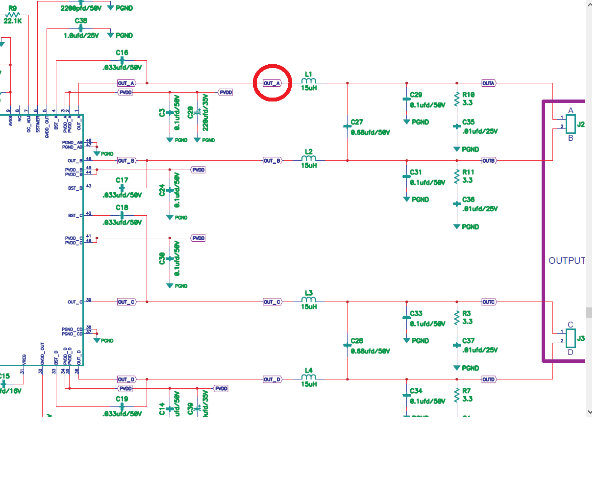
  • Where can I probe to monitor the PWM signal on EVM?  GND pin on the J1 connector of MC57xxPSIA board and OUT_A at the L1 inductor?

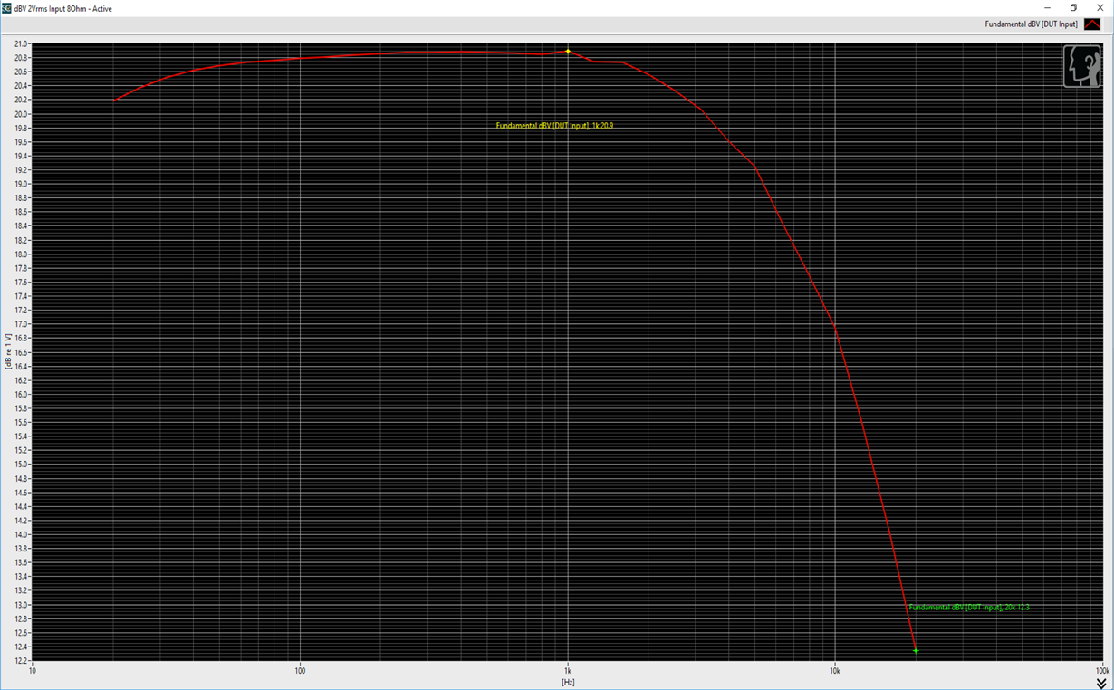
  • Did some measurements on the TI 5707 amp and there seems to be a large HF roll off, about 9dB from 1k-20kHz.  Used 2Vrms analog input (with Jp2 & Jp3 not shorted) which gives an output of about 11Vrms at 1kHz.  This is with 24V supply and 8 Ohm load.  Is this expected?

  • Hi Michael,
    Yes, OUTA is the PWM output from the device.
    Best regards,
    Shawn Zheng
  • Hi Michael,
    I think the high-pass filter effect is expected. DC is harmful to the speaker, so there is DC block filter inside the device to avoid the speaker from being damaged by the DC signal.
    Best regards,
    Shawn Zheng
  • What I am observing in the plot posted is a low-pass filter, filtering out high frequencies (1k-20kHz -9dB or 7Vrms).  I didnt think DC has an effect on High frequencies? 

  • Hi Michael,

    Sorry for the my misunderstanding. For the high frequency(1kHz~20kHz) loss, it's not expected. You are using TAS5707 EVM, right? LC filter on the board is in the default setting, right? Becasue too low LC filter cutt-off frequency may supress the high frequency components. Please also check you BQ setting is set to 'All-pass'. And you could also disable DRC for this testing. The frequency response should be very flat across the audio band.

    Best regards,

    Shawn Zheng


  • Thanks for checking back.  Yes I am using TAS5707EVM. Is there a jumper that configs the LC filter in default setting for EVM?   I have set BQ to All Pass and set DRC to disable. 

    I am connecting +/- of signal generator (Listen AmpConnect) to RCA analog input and output terminal A as +, B as - to 8 Ohm dummy load and that to analyzer input (Listen AmpConnect).  Anything wrong with my setup?

    Thanks

  • Hi Michael,

    There is no jumper for the LC filter setting. I mean the LC filter is still 15uH+0.68uF(there is no change on the EVM), right? I can't see anything wrong in your measurement setup. Please double-check the instrument setup, make sure there is no LPF added in the setting or the bandwidth of LPF is higher than audio band.

    You could do a simple experiment: apply a 1kHz single-tone waveform, then measure the RMS value on the output. Repeat this with a 10kHz single-tone waveform. The result should be close between these two measurement. 

    Best regards,

    Shawn Zheng

  • To what I can tell, referencing the schematic on the EVM guide there is the 15uH inductor physically on the EVM and there is a small SMD capacitor labeled C27 (capacitor value difficult to tell on EVM). 

    Again there is still a 4 Vrms difference between a 1kHz sin tone & 10kHz sin tone.  See attached xlsx sheet with amplitude sweep measurements.  Could you check this on a board you have in in your hands? 

    TAS5707_ampSweeps_HF_attenuation.xlsx

  • Hi Michael,

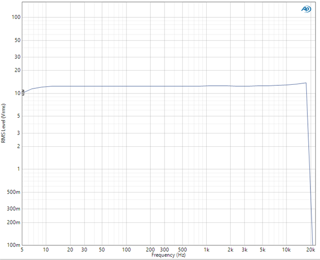
    Please find my measurement result (based on 24V PVDD, 8Ohm load, TAS5707EVM) in below.

    Input signal is applied by OPTO connector. The output is around 12.4Vrms, and it's very flat across the audio band. The depression around 20kHz is caused by AES17 20kHz filter which I enabled on AP instrument.

    TAS5707 is very popular in the market and has already been very widely used. We never heard of this issue before. Please debug your measurement setup.(e.g. the filter setting in your instrument...)

    Best regards,

    Shawn Zheng

  • Hi Michael,
    Plesase let us know if you have any other question here. Please help to close it if you don't more other question. Thank you.
    Best regards,
    Shawn Zheng