This thread has been locked.

If you have a related question, please click the "Ask a related question" button in the top right corner. The newly created question will be automatically linked to this question.

INA225

Other Parts Discussed in Thread: INA225

Hello:

I'm using the INA225 eval board. Using a 5V supply, An array of resistors of 0.05 ohms as shunt  and a load of 5.45 ohms. Based on calculation my voltagedrop shoud be around 45mv  but  I'm reading 56mV in the TB3 of the eval board. If I disconnect the circuit and test it w/o the eval board I get the right values.. Why the Eval board is adding 10mv to my measurements.,

 I try other shunt values and current values and I have the same behavior.

Thanks

Raul


  • Hi Raul,

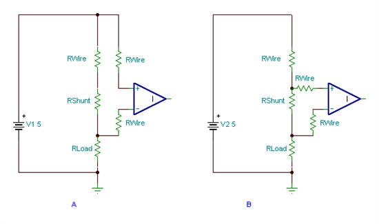
    I was able to duplicate a similar experience and attribute the extra voltage drop to the 1A of current flowing through very small gauge wire I used in an attempt to recreate the issue...a voltage drop of 10 to 15mV was observed across the wire (approximately 6 inches in length).  Are you possibly seeing a similar issue?  Schematically this is what I observed...

    in Schematic A I create the additional voltage drop across the length of wire...in Schematic B I connect the inputs more directly to the shunt resistor...the wire resistance in series with the inputs makes no difference in either schematic, but in Schematic A the wire resistance that has the 1A of current flowing through it appears as a differential signal....in Schematic B by virtue of the improved connection the same voltage drop across the wire is now a common mode signal and no longer a differential signal.  Please let me know if you are experiencing a similar issue with the wiring connections...

  • Thanks for your response Edward:

    The wire length on my circuit is just an inch (resistor terminal only) from for my shunt. One thing that I observed is that if I remove the amplifier the additional 10 mv goes away. I did another expermiment just drawing 300mA and have the same 10mV additional to my regular voltage drop in the shunt.


    Raul

  • Hi Raul,

    Thanks for the additional information...is it possible for you to send me a photo of your setup?  From this photo, I'd like to be able to see any high current paths, how the inputs are connected when the problem exists and how the board is configured.  If you prefer you may also send the image direct to my email.

  • Edward; Thanks for your help. I change my supply cable and the problem was fixed.  Also I decice to reduce even more my cable lenght as much as possible and now works just perfect.. Now I have to make sure that the real application my shunt is as close as possible to the amplifier.


    Thanks

    Raul