This thread has been locked.

If you have a related question, please click the "Ask a related question" button in the top right corner. The newly created question will be automatically linked to this question.

INA138 in current control loop

Other Parts Discussed in Thread: INA138, INA282

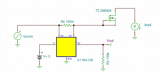
I am attempting to utilize the INA138 as a current monitor in a closed loop proportional valve controller. My output current is delivered from a high side FET which receives input from a PWM. Due to the nature of the valve, as current is applied to it, its resistance changes due to heat rise. As a result, I need to monitor the current applied to ensure constant current is output from the FET. 

When I apply a substantial amount of current (300mA) I obtain reasonable readings from the INA138 (right now I am measuring on a multimeter but once I get this issue figured out will be inputting the signal to my microcontroller). The issue comes from the lower currents (below 300mA). When I read the voltage at Pin1 (Vout measured across a 150K resistor) I obtain negative voltage readings. My Rs is currently .1 Ohms meaning my Gain is appoximately 3 since I want my max reading of 1A to read 3.2V.

What is causing my reading to be negative at low current? I have the INA138 connected inbetween the load and the FET (the high side). If necessary, what other current sense amps reliably measure currents between 0-1A?

Thanks,

Adam

  • Adam,

    At first look, I believe I understand your setup will have 300mA through a 100mOhm shunt resistor, correct?  If this is the case, then the voltage across the shunt will be 30mV.  Looking at the "Total output error vs Vin" plot on page 4 of the data sheet, you can see that the total output error % drops off at 25C somewhere around 15mV-20mV.  I wonder if this is the effect you are seeing.

    From your description, I drew up what I think your circuit looks like, can you confirm?

    I will look into this further and see what my colleagues think could be the issue, and if there is a current shunt monitor that may fit your needs better. 

  • Jason,

    The above is actually what my connection looks like, The INA138 is measuring current output from the FET to the valve (represented by the inductor). I have a diode in place in parallel with the load to protect the FET from damage.

    Thanks for the support.

    -Adam

  • Hello Adam,

    I would like to clarify your configuration.  What voltage is the V+,Vin,Vin+ and Vin- of the INA138 and at lower currents with respect to ground of the INA138?

    Regards,

    Sensing Aplications

    Jamieson Wardall

  • Jamieson,

    V+ is 5. The voltage across Rs (Vin+ - Vin-) is anywhere between 8 mV to 110mV depending on the duty cycle of the PWM input to the FET. My readings at Vo only begin to make sense when the voltage across Rs is about 50mV, which is what the datasheet suggests, however I need to be able to accurately measure those lower currents in addition to currents up to 1 A.

    Thanks,

    Adam

  • Hi Adam,

    I think that the lower PWM cycle of the FET at lower currents is causing a negative common mode voltage at Vin+/- which would give you a negative Vout.  The common mode voltage can't drop below 2.7V.  Can you send me the schematic of the DC-DC system?  This will help me understand the topology and better assist you.

    Regards,

    Jamieson

  • Jamieson,

    I posted a schematic a few posts up. Basically I am measuring the high side current output of a high side switch powering a proportional valve. I have switched my Rs to .2 Ohms in order to achieve a higher voltage across the INA138 inputs (I also changed RL to 75K to keep the same gain) and seem to be getting better results, although still not as accurate as I need. 

    The datasheet states that I do not need to filter the output, but should I consider it, given the low voltages I intend to read across the inputs?

    Regards,

    Adam

  • Hello Adam,

    Due to the common mode voltage going below 2.7V when the FET shuts off and current is flowing through the coil, I would suggest a device with a much wider common mode range.  The INA282 has a low common mode voltage down to -14V. The reference voltage can also be adjusted to set the output too.

    Filtering the the output will only be helpful if the correct common mode voltage is met.  I hope this helps.

    Regards,

    Jamieson

  • Jamieson,

    I have purchased the INA282 and replaced the INA138 with it in my circuit. When the FET is switched on, the OUT pin reads 4.5V regardless of the current output.

    Reading Vrs (rs equals .1 Ohms) I get the following for each of my 10 output levels:

    Setting 1: 24mV 

    Setting 2: 33mV

    Setting 3: 41mV 

    Setting 4: 47mV

    Setting 5: 54mV 

    Setting 6: 62mV

    Setting 7: 67mV 

    Setting 8: 73mV

    Setting 9: 79mV 

    Setting 10: 93mV

    I have both Vref pins connected to GND and V+ is connected to +5V.

    Any thoughts?

    -Adam

  • Hi Adam,

    Sorry for the delay in response here and sorry for switching again who is responding to your question...I am the team manager and we have some team members out on vacation and I saw that this issue is not yet resolved for you.  Have you looked at the typical curves in the INA282 data sheet, specifically the typical curves that show the response to various common mode transient inputs?  The reason I ask is that the INA282 is a sampled system with a particular internal sampling frequency and as such you may get unpredictable results if your common mode voltage is moving up and down from 12V to 0V (or even a bit negative) within the sampling period...in the case of a 12V common mode step it takes about 25uS for the device to settle back into its correctly regulated state...if you are switching multiple times within that 25uS period it may be causing this issue.  I assume that you have already verified that the power supply to the device is biased properly, the ground is actually connected to ground and not by some chance floating, etc, similar to that shown in Figure 34 of the data sheet.  If you can provide a typical waveform for what you see at the common mode input (+IN pin) I can recreate that in our lab and see if the device will work properly in your application or not.

  • Edward,

    Thanks for your response. I have checked my ground points (and as a result my reference inputs which are connected to ground) and they are in fact connected to ground. The waveform at the input pin is roughly a square wave with an amplitude of 12, a period of 1 ms, and the duty cycle varying from 20% to 80%. I am able to vary the period of that waveform if necessary.

    Regards,

    Adam

  • Hi Adam,

    Thanks...from the data sheet here is a figure showing the response to a step in common mode voltage...where are you sampling the output relative to the transient disturbance from such a common mode step input?

  • Hello Adam,

    I am back from vacation.  Were you able to solve your issue?  Let me know if you need help.

    Regards,

    Jamieson Wardall

  • Edward,

    I am not sure I understand your question, the waveform I described in the previous post is measured at the output of the FET where the current sense resistor would be.

    Regards,

    Adam

  • Hi Adam,

    Ed is asking, when in time are you making the measurement?  When the common mode voltage steps (FET turns on or OFF) how long do you wait to make a measurement?  On the graph, it take approximately 16uSec for the output to be stable after a 12V step of the common mode voltage.

    Regards,

    Jamieson

  • Jamieson,

    Currently I am taking a measurement with a multimeter so the reading isn't' made until the FET has been on for a few seconds. 

    -Adam

  • Hi Adam,

    When you say, the FET is on, do you mean in a static DC state or is the PWM input to the FET on?  If there is a PWM input to the FET, you must wait 20uSec for every step (FET off to on or on to off) to let the common mode voltage stabilize before making a current measure.  Do you have access to an oscilloscope?

    Regards,

    Jamieson