This thread has been locked.

If you have a related question, please click the "Ask a related question" button in the top right corner. The newly created question will be automatically linked to this question.

INA 226, problem with shunt voltage triggered mode

Other Parts Discussed in Thread: INA226

Hi all,

I have a behaviour than I don’t understand with the INA 226.

I use an INA226 demo cards.

I want to measure the shunt voltage every 1024 (Averaging mode) * 8.244ms (Conversion Time) with the Shunt Voltage, Triggered mode.

Here is the algorithms used:

=>    Begin  

|

=>    Write in configuration register

|

=>    (1) : Read Enable/Masked register

|

=>    if CVRF (Conversion Ready Flag) == 1 then go to (2)

|

=>    if CVRF (Conversion Ready Flag) == 0 then go to (1)

|

=>   (2) : Read the Shunt Register

|

=>    End


I launch this program in a loop and display the value measure. Then I expect to receive a sample every 8.441 seconds but the period of the sample measured appear randomly. The time is including between 0.5s and 6s. In the other end the value measured in the shunt register is good.

Furthermore when I read on the Mask/Enable register I have values than I don’t understand who can be :

03FF

000F

0031

07FF

007F


I’am blocked and I don’t know what to do to receive the sample every 8.44s when I launch the measure as I expected.


Thank you for your help.


  • Hello Florian,

    How many averages do you want and how long do you want the conversion time for the shunt and bus (they do not need to be the same values)?  I would recommend triggering on both shunt and bus to keep the measurements synced up.  Continuous mode can be used also if you are making sampled measurements that do not need to be synced to a any period in time.

    Example:

    The shunt voltage conversion time could be set to 4.156ms with the bus voltage conversion time set to 588μs,
    with the averaging mode set to 1. This configuration also results in data updating approximately every 4.7ms.

    Note:  For triggered conversions, the configuration register must be written to for every conversion sequence.

    Note:  If the device is running a conversion and the configuration register is written to, the current conversion will stop and the new conversion will start.  This means that if you are running in continuous mode then write to the configuration register to change to triggered mode the current continuous conversion will stop and the new triggered conversion will start.

    Regards,

    Jamieson Wardall

    Sensing Applications


  • I’am not sure to give you the good explanation. I try to give you a better explanation of my problem.


    I would like to do 1024 average with 8.244 ms of conversion with the mode “Shunt Voltage, Triggered”. In fact the application I’am working on use just the shunt voltage. The bus voltage is not use in my application it’s why I choose the “Shunt Voltage, Triggered” mode.

    So the value write on the conversion register will be : 0x0E39.

    Also I don’t use any option on the Mask/Enable register. So the value at the beginning is set at 0X0000.

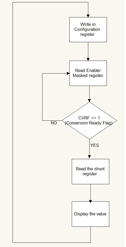
    May have a look on the diagram bellow :

    As you can see I’am reading the Mask/Enable register to check the conversion ready flag.

    So the program is normally waiting until the conversion ready flag switch to 1, I will not normally writing something into the configuration register until the currently measure will finished.

    It’s exactly what’s happen but not with the 1024(average) * 8.244 (ms) = 8.441 seconds I expected. In fact the measure is taken in random time who can be sometimes 2 seconds or sometimes 0.5 seconds.

    So I look at what happen on the Mask/Enable register and the value measure are a little bit crazy and can be : 0x03FF, 0x000F, 0x0031, 0x07FF, 0x007F.

    It’s what I do not understand why I have this value on the mask/enable register and where do that come from ? I may be make a mistake somewhere.

    Also I try in continuous mode with different time of conversion and average and the value measure is good and look to work properly. So I just check the Mask/Enable register without using it and its value measure look to be the same.

    I hope it will be easier to understand my problem now.


    Regards.

  • I forget to mention : I expect to have the value 0x0008 into the mask/enable register when the conversion is finished.

  • Hi Florian,

    Instead of writing 0E39 write 4E39.  I am writing 4E39 and the demo board is setting the conversion flag ready at approximately 8 sec.  Let me know if this fixes the issue.

    Regards,

    Jamieson

  • Also, check that reading back the configuration register is 4E39.  If it is not, the device may be damaged.

    Regards,

    Jamieson

  • Hi,

    I just write 4E39 on the configuration register. I read the value each time I write on it and the value is always good.

    But infortunatly the problem is steal there the value on the Mask/enable register don't mean nothing. And the time between two sample is still apearing randomely.

    Regards

  • Hi,

    Let's go through what pin voltages are set at.  Tell me how you have the device configured.  Is this the EVM board or a different design?

    A1=

    A0=

    SDA / SCL pull up resister value and voltage

    Vs=

    Vbus=

    Vin -/+=
     shunt voltage, current and resister value and configuration register value.

    Regards,

    Jamieson

  • I'am using the EVM board.

    A1 = 0

    A2 = 0

    SDA SCL pull up resistor value : 2.2k

    SDA SCL voltage value : 5V

    VS = 5V

    Vbus is not connected

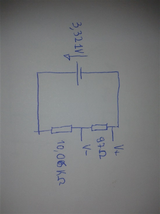
    Vin = -0.031 V

    Shematic :

    Register :

    - Shunt Voltage : -0.031455

    - Configuration register = 0x4e39

    Here is all the informations asked.

    Regards

  • Hi Florian,

    I was able to reproduce your results by floating Vbus (not connected).  Connect the Vbus pin to GND and try running the program again.  This should solve your issue.

    Regards,

    Jamieson

  • Hi Jamieson,

    I put Vbus on GND and nothing change, the value are still appear ramdomly.

    Have you got an other idea ?

    And many thinks for you help.

    Regards

  • Hi Florian,

    OK, I think we should reconfigure to a known state.  Setup your board as follows:

    Pullup resistors R3/R4 should be 10k ohms

    Jumpers:

    J2 set to INT

    J3 set to GND

    J4 open

    J5 set to GND

    J6 open

    VBUS short to VS

    VIN- short to GND

    Apply 20mV from VIN+ to VIN- current limit to 10mA

    No resistors on VBUS or VIN+/-

    Software:


    Set VS to 3.3V

    Configuration Reg= 4123

    Calibration Reg=  0A00

    Let me know if this works and we can change the setup from here.

    Regards,

    Jamieson

  • Hi,

    After several measure. The probleme come form the driver I'am currently using. I'am going to make some modification into it and let you know about the progress.

    Regards.

  • After several try. The probleme should come form the driver I'am currently using.

    But In the other hand I want to try what you ask me :

    "Pullup resistors R3/R4 should be 10k ohms"

    On the datasheet, the bill of Material indicate 300 ohms for R3/R4. Do I have to change it ?

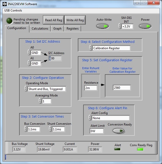
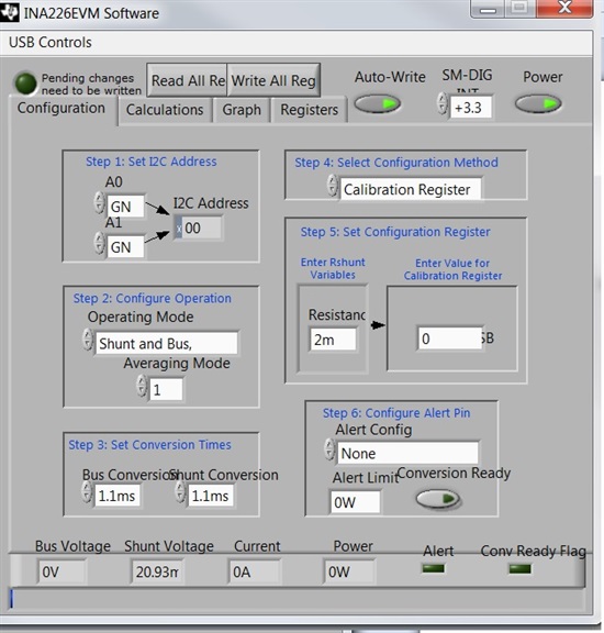
    Here is the screenshot of the measure taken with the configuration show above.

    As you can see the Conv ready Flag stay off. Even if I press the Read All Reg button several times. If I do it on conversion mode the Conv Ready Flag goes on.

    Let me know if you have any idea, I'am still looking for the driver.

    Regards.

  • Hi Florian,

    What driver are you currently using?

    The BOM is incorrect R3,4 should be 10k ohms (I measured the EVM to make sure).  Can you measure them?

    Can you setup you configuration identical to mine?  I see that the calibration register is blank (it should be set to 2560).  Also, trigger off of both Shunt and Bus.  Tie the Vbus pin to Vs on the board and tie VIN- to GND.

    If this isn't working, I think a phone call would be a good, so we can walk through the setup together.  Let me know when you are available and we can coordinate a phone meeting.

    Regards,

    Jamieson