This thread has been locked.

If you have a related question, please click the "Ask a related question" button in the top right corner. The newly created question will be automatically linked to this question.

INA282 sense formulas & suspected ESD protection blows 15 amp SMT fuse.

Guru 54087 points
Other Parts Discussed in Thread: INA282, LM3S8971

This seems to be either not related or directly related to the INA282 causing a 15 amp bridge fuse to blow when B+ 169 DC is switched on.

To be clear 3 common mode shunts are monitored per page 24 figure 42 at the source of three FETS with individual 018 ohm current shunts very near ground potential on pin 1 & 8. The supply voltage of the INA282 is set at 2.975vdc providing an output center near 1.488 volts. The low/high side FETS gates are held low by three bridge drivers pre-powered from an isolated supply voltage before the B+ is switched on which then instantly blows the fuse.

Recently switched over from using 3 Opamps feeding into 3 separate ADC channels monitoring the three shunts which worked ok at 169 B+. The INA282 shunt monitors without blowing the fuse when (B+ is 20 VDC). Even after blowing the 15 amp fuse (B+169) several times the INA282 keeps on functioning as if nothing hazardous has occurred. After the fuse is replace and INA282 is tested once again to be functioning ok (B+20v).

Although the text states common mode limit of 80 volts, it is the posters belief the INA282 shunt input pin never should see anything close to 80 volts common mode being protected by each low side FET source, drain is 200BDV.  

The INA282 data sheet page 24 states low side current monitoring has the added advantage of not be subject to any common mode transient artifacts.

1. Is switching on the 169 volts B+ such a transient to the INA282 and how can this blow the fuse?

 2. Will adding a snubber diode (MUR300) cathode on pin1 or 8 to ground act as a transient suppressor without effecting the output signal or should a 75-78 volt zener be added?

Thanks for any ideas and or suggestions.


  • BP101,

    Thanks for the information - would it be possible to share a schematic (either here or through email, if you don't want it publicly accessible) so we can see exactly where the fuse(s) are placed and be able to look up the specs on the components in the circuit if needed?

    With regards to transients affecting the INA282, yes they will affect it.  Excessive transients often damage the device because the silicon process cannot handle the potential.  Transient protection is absolutely something to consider including; see the INA210 data sheet, pages 17-19 for a discussion on transient protection with some example circuit implementations.

    Thank you,

    Jason Bridgmon

  • Hi Jason,

    The bridge shunt monitor & diagram in play are shown on page 12 & 24 of the INA282 data sheet. Pin 8 is tied directly to the ground plane and pin 1 to the low side FET source and shunt resistor junction. This is a prototype, high voltage exists on PCB atop an RDK. No schematic exists other than the basic bridge design used in the Stellaris LM3S8971 RDK. The 6 FETS are Fairchild (FDP52N20) 49 megohm 200 VDC. 

    The 15 amp fuse does not blow when using 3 Opamps on the lower RDK to monitor the 3 shunts top side at 169vdc bus voltage.

    The main question is does the INA282 when located on the low side FET driver shunts ever see 80 volts common mode supply potential? 

  • Hello,

    I wanted to confirm, the shunt is 18m Ohms?  With 18m Ohm the shunts should never have more than half a volt across the shunt.

    The Stellaris schematic has an amplifier with a resistor divider 10K&1K, 3.3V to the divider and a gain of 3.79.  I think the current being misrepresented so that the PWM signal is driving more current.

    What are REF1 and REF2 set to and how did you set the gain in the software to account for the gain difference?

    Regards,

    Jamieson Wardall

    Sensing Applications

  • Hi Jamieson,

    That would be 0.018 ohms and the INA282 on upper PCB does not use the operational amplifier circuits input divider or any of the shunt sense circuit located on the lower PCB.

    Besides the PWM in not even asserted - merely turning on the higher voltage immediately blows the fuse.

  • Again the INA282 data sheet states low side sensing is not subject to shunt monitored transients.

    However, sensing on the output is subject to large common-mode voltage steps that result in feed through in even the best amplifiers. The ground and supply-side sensing configurations are free of this problem, thanks to the static common-mode environments. Sensing either ground or supply alone only provides partial information regarding motor current, but sense them individually and sum them and we have the same information provided by phase sensing, with an added advantage of not being subject to transient common-mode artifacts.

    Quite possibly something has gone wrong in the ESD input protection reacting to voltages below the documented ESD range. Input protection would take any stray ESD directly to ground when it reached the transient threshold. Hence blowing the 15 amp fuse.

    In this case the INA282 circuit is partially under low voltage power 2.975VDC and the phase drive outputs are roughly 4.5-7VDC to ground prior  of 169v B+ being switched on. Up to the point of installing the three INA282 in the upper PCB this topology was functional using Opamp shunt current sensing found on the RDK. There are no shorts detected across the input B+ measured beyond 55 megohms and the circuit works when powered B+ of 20VDC.

    This finding tends to point to a INA282 protection device incorrectly reacting to a perceived transient condition?

  • Hi,

    From your previous post you had stated that the 3 INA282 aren't damaged but that the 15A fuse blows.  If the current was going through the INA, they would be damaged as they can not handle but 5mA on any pin (page 2 ABS Max).

    What OPAmp were you using for the current measurement?  The Stellaris BLDC kit design was using a FAN4174IP5X (only rated to 5V) which was directly fed into the ADC of the LM3S8971.  Are you using the Stellaris BLDC kit?

    I am not understanding upper and lower PCB.  Is the INA282 directly next to the shunt?  A hand drawn schematic would help me to see what you mean by upper and lower PCB.

    Regards,

    Jamieson 


  • That seems to be a good point 5ma any input pin including ESD protection?  Stellaris RDK kit is lower PCB.  We added a high voltage bridge driver PCB over top the RDK, the FETS & bridge drivers removed from RDK.  Yes the INA282 pin 1 trace is less than 1/4" from the shunt resistor.  Oddly the configuration was working at 169VDC with the RDK Opamps the upper PCB shunt monitors being feed on isolated ribbon down to lower PCB. This all changed after installing three INA282 into vacant positions on top PCB very near those shunts. All three INA proved by an excellent signal shown in scope photo. Rechecked over and over for any solder splash low or high resistance shorts, none to be found.

    Was considering removing the INA282 power to test if the inputs go high impedance state. That should remove the potential to blow fast reacting 15 amp fuse if perchance the ESD part is not limited by the 5ma rule. Then turning on the INA282 V+ pin after the 169v B+ is stable???

    8/20 The fuse still blows so the ESD is not disconnected when the inputs are in high impedance.

    Top reference 5200 RPM motor - lower reference motor below 100 RPM:

  • Hi,

    Now I understand the top bottom PCB. 

    Was the ribbon cable only used for the shunt or anything else?

    When you power the 169V what are the gates of the FETs being driven to? 

    What is the next sequence to start the PWM? 

    Can you remove the IN282 and power-up without them installed (no current measurement)?

    Maybe a phone call would be a good idea.  My email is jw@ti.com

    Regards,

    Jamieson

  • Each shunt output into Opamps input resistors was on individual 2 wire grounded ribbon. Each INA output feed to lower PCB for the ADC inputs are 2 wire individual grounded ribbon as well.

    The FET gates are kept in the idle low state by the Fairchild 1/2 bridge drivers. BTW forget to mention a 30 volt zener exists across each gate to source high/low side.

    We then click on run in the GUI starting the motor.

    Removing the INA would be near impossible existing under the low side 3 copper heat sinks. Cutting the input trace to pin 1 very simple indeed.

  • Hi,

    So you would cut the trace to pin 8 as pin 1 is attached to GND right?  See page 25 figure 43.  1 Vin- is GND and 8 Vin+ is to the source of the FET.

    Regards,

    Jamieson

  • For other readers this post went to a land line conversation shortly after. The diagram on page 12 labels pin 1 to be (load) suggesting it face the FETS source with pin 8 labeled (-14 to 80v) connects to ground. Page 24 refers figure 43 page 25 explains summing H/L rail will avoid common mode transients.

    Some confusion here because we sense 3 low side shunts individually sum the readings in software then multiply & divide for an average RMS current. That is believed to have nearly the same effect as would adding more hardware versus using software to accomplish the same task.

    So in fact sensing the low side alone from a hardware perspective (page 24) is subject to CM transients.

    This case electron current flows from ground through the shunt back to B+ and any reverse current (hole flow) B+ to ground. Typically myself seldom use the conventional current flow theory unless the word (reverse) is noted somewhere in the data sheet. Those wondering what are (holes), recalling are depleted electrons returning home.

    Cutting pin 1 trace away from the three shunts did not stop the 15 amp fuse from blowing once again. However pin 8 was still connected and possibly the three IN282 will have to be removed.  To be clear all 6 FETS (DS) junctions free wheeling diodes measure very closely .516v drop. Driving a small BLDC motor the PWM signals appear on the oscilloscope very clean, no voltage level or edge anomalies on any phase can be found.

  • Have an possible answer for the blowing fuse. The IN282 may some how be changing the current flow upon switching on 169v B+. The 15 amp fuse rated 125VDC break point 300 amps worked with Opamps current sensing but not with INA282. The 10 amp fuses originally being used on the power PCB were rated 350VDC with a 56 amp break point but often popped well under a reported 9 amps set as maximum BLDC current. Having one last 10 amp SMT fuse to install and it held for the INA282 switching on the 169v B+ but shortly blew upon running the larger BLDC motor.

    In hind sight the RDK power formula and Opamps sensing circuit seemingly could have been misreporting the actual current and wattage showing it to be far greater than what in reality was being produced or even required by the BLDC motor.

    Sunday installed an inline 10 amp 250v AGC fuse, arresting the very rapid fuse blowing symptom for goodness sake.

    The INA282 datasheet has no formula to help explain the amps/volt a particular shunt 18m ohms would produce on the output pin. The output center set at 1.488-1.490 volts, Ref1,V+2.975 shown above. The current is behaving very differently with INA282 and the BLDC under load seems to have more power fewer watts. The INA282 sense current appears move sine wave shaped than with Opamps. Less heat is now being dissipated by the BLDC doing the very same work as before.

    The running voltage across Rs (DVM) .480-.530mv DC or .050mv peak with a gain 50/(Ref1 +2.975) = 16.8?


  • Hi,

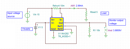
    For the typical INA282 application with Vout=(1/2)*V+:

    REF2=V+

    REF1=GND

    Vo= (Isense*Rsense*50)+(1/2)*V+

    Isense=(Vo-(1/2)*V+)/(Rsense*50)  This is for current flowing from IN+ to IN-

    Regards,

    Jamieson

  • Spent some time measuring the shunts drop again under load conditions both DVM and Oscilloscope. 

    Really appreciate the INA282 ratio metric AC current sensing, appears more accurate than measuring a DC voltage rise fed into an ADC. The INA gain seemingly works out to be 16.8 or 50/V+2.975 being no input pre-bias exist on pin 1 and the internal difference amplifier bias is +2.975 renders roughly a .7%.error accuracy, not bad at all!

    Seemingly 7mv DC was being detected across the .018 ohm shunts rising to .029mv DC, .037mv AC by way of DVM. The oscilloscope across shunt shows a larger steady state amplitude, suspect  true RMS DVM to be *.707 peak. Hence the DVM is much easier to follow than a shunts complex analog signal displayed via an oscilloscope.


    Thanks again Jamieson :)

  • Estimating the INA282 sensitivity at 16.8 gain to be (.001109uv/amp) with a .018 ohm shunt. The ADC current formula and limiting code averages the INA output. The running motor current averages 1.6 AC amps cycle/cycle current limiting at shunt drop of .038ma (AC coupling). The motor current peaks near 3.2 amps.

    Motor current limiting is periodic and not the same as DC input current measured via DVM 4.1DC or 1.7AC amps.

    With a shunt of .005 ohms expecting the stator current limiting to be roughly 2.5 amps @ .012mv shunt drop. That stator current limiting average tends to double giving 5 amps AC peak current. Expect the supply linear current will also increase in similar manor but there is head room for much more average stator current.

    The net gain of the INA282 over using Opamp for low side current monitoring becomes suddenly visible in motor efficiency. The motor current seemingly is more AC periodic, the DC supply current SOA is 2x the motor current.

  • Added soft start into 170v DC B+  by simple 330 ohm 10watt series resistor across DPST B+ switch contacts returning the solder bridged pads to a 15 amp onboard fuse.

    Still not clear why this symptom occurred right after installing three INA282 current monitors.

    However there was later found to be significant inrush current charging a 470uf 200v capacitor. Notable a 20mm round un-melted solder bridge across pads, a home grown (fuse). Occasionally even this fuse exploded leaving the power supply B+ 10amp fast fuse intact. That loud pop tends to get ones attention to do something a bit safer at some point.