This thread has been locked.

If you have a related question, please click the "Ask a related question" button in the top right corner. The newly created question will be automatically linked to this question.

Offset and oscillation with INA226

Other Parts Discussed in Thread: INA226, INA226EVM

Hi everybody,

I hope you are well.

I try to measure the current through a resistance of 4mOhms. I notice an "osciallation" of 550uV and an offset of 300uV. The osciloscope is not enough precise to display this oscillation. I'am using the evaluation board. The device is used in shunt voltage triggred mode with 1 average and 140us conversion time.

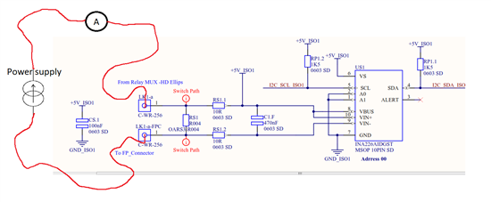
Here is the layout :

Here is the measure obtained :

Current (mA) measure by the DMM

-2010

0

1992

Current(mA) measure by the INA226

-2055 to -2194

9.76 to 43.9

1922 to 2073

Current(uV) measure by the INA226

-8225 to -8780

40 to 300

7697 to 8295

If you have any question let me know. I expect to have a more accurate value.?

Thank you for you help.

  • Florian,

    For whatever reason, the image you posted isn't visible to me. Would you please insert the image again, or maybe use the attach button at the top of the edit field, or email or to me directly?

    Thanks! I look forward to helping you! 

    Jason Bridgmon

  • Florian,


    Yes you are getting results that are not consistent with the INA226 specifications.  I have a few questions regarding your setup and measurements -

    1. Where and what is the load in your schematic?

    2. When you say Current (mA) and then Current (uV) - are just showing me the math?  (i.e. 0.0003V / 0.004oHms = 75mA?  The numbers you show don't line up which is what is confusing to me.

    3.  You say you are sampling in triggered mode - are you sure it is an oscillation and not noise in your system?

    4. How are you connecting your oscilloscope?  Are the leads tied directly to pins 9 and 10 of the INA226?  I think this would be the best representation of what the INA226 is seeing.

    5. Could I see the layout of the board - at least the piece in question?  Sometimes excessive trace length can hurt performance.

    6. Are there other devices powered on +5V_ISO1 that could be affecting the power supply output?


    7. Have you tried using more averaging than 1, or a longer integration time?

    Regards,

    Jason

  • 1 : I have no load, a power supply is used as a current generator.

    2 :The tension is measured by taking the shunt resistor value and multiply it by 2.5. The current is taken by multiply the current register by the currentLSB. It's why may be we don't have the same value

    3 : It could be a noise of curse.

    4 : I connected the first channel to Vin+ and the second to Vin- I then use the function math to substract First channel by the second.

    5 : I'am using the evaluation board I just add the filter connect vbus to 5V and connect the 5V to Vin+ to simulate the future layout

    6 : no

    7 : yes the problem is still there

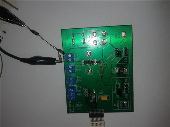
    To simplify the purpose I change the montage wich I have exatly the same problem. I'am using the evaluation board. Without any filter. You can see it bellow :

    The DMM measure 29.7 mV. And the result I get with the INA226 oscillate between 29.337mV and 31.127mV.

  • Hi,

    I try with the montage above and the INA226EVM software. Here is the result :

    The device's oprating mode is on Shunt voltage continuous. And the value measure by the DMM is 33.5 mV.

    Averaging mode     Value

    1                             32.67 to  34.23 (mV)

    512                        33.74 to 33.84 (mV)

    I hope that this value can help you to understand the problem.

    Regards.

  • Florian,

    At first glance, that does point to noise in the system.  Considering the average of 512 points gives you a 100uV variation and 1 point gives you 1.56mV variation, that is certainly something to look in to.  I think that what you have set up is conceptually correct but I'm starting to think that maybe something in the physical realm is causing variations.

    Could you share a photo of your setup?  I would first start looking for things like excessively long wires.  Since the current between the device and the shunt is fairly small, it could pick up transient noise from the environment.  My email is bridgmon_jason@ti.com if you want to keep anything private.

    I also wonder if you might consider adding the filter components to the EVM board to smooth out the signal and cut down on noise.

    I'll also ask my colleagues if they have any ideas for other potential noise sources in your setup.

    Regards,

    Jason Bridgmon

  • Hi,

    Here is the picture :

    I made futher changement as you can see, change several time the chip, and try different filter.

    I order a new card to see if I domage it.

    Regards.

  • Hi again,

    I just recieve the card when I send the mail.
    It still very noisy. I'am going to try with a filter. And i let you know.

  • To reduce te following filter have been used :

    R1 = R2 = 10 Ohms

    C1 = 470pF.

    Infortunatly the noise is still there.

    Instead of using the power supply a battery have been used. The noise disapear completly. Then it come form the power suply. 

    Have you got an idea how to reduce this noise without take 1024 sample in averaging mode ?

    Many thanks.

  • Please send me the manufacturer and model number of the noisy supply you are using. I will see if there is anything I can recommend.  I also asked my colleagues if they have any noisy-supply tips to give.

    Jason Bridgmon

  • Shenzen matech. DC POWER Supply HY3003D-2.

    Thank you for you help Jason.

  • Florian,

    I found some specs on your supply; on paper it looks good but in practice it appears to be noisy.  What is the end application for this circuit?

    What is your current source referenced to?  I'm thinking that if it isn't attached to ground somehow that the common mode may be causing issues and VBUS, which is referenced to ground, may be inaccurate as well.

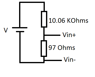
    Another thing to look in to is the 97 ohm shunt.  This is very inadvisable as the input bias current is 10uA, and that will cause 1mV of error right away.  It may not be noisy but it will be inaccurate.

    Also try reducing the length of the cables between the supply and the shunt.  Remove other EMF noise sources from the area, and measure the noise at the inputs of the INA226.  if it's moving by 1.5mV as you suggest, you should be able to see that.  Let me know how it goes.

    Regards,
    Jason Bridgmon

  • The futur application will be to measure the current as an ammetter through a resistance of  4 mOhms. I will not use vbus then. You have the layout just above. Futhermore if you notice something bad on this layout do not esitate to tell me.

    The current source is referenced to the ground.

    I took some measure with the resistance of 4 mOhms and different averaging :

    Voltage measure by the DMM :- 8 mV

    Number of sample

    Tension measure (mV)

    Level of noise measure (mV)

    1

    -7.313 to -8.045

    0.732

    4

    -7.505 to -8.053

    0.548

    16

    -7.86 to -7.95

    0.09

    64

    -7.86 to -7.93

    0.07

    128

    -7.865 to -7.885

    0.02

    256

    -7.868 to -7.888

    0.02

    1024

    -7.863 to -7.887

    0.024

    As you can see without the averaging the level of noise measure is high.

    The wire have been reduce and is true thant the noise is lower.
    With the resistance of 0.004 Ohms and with a Number of sample of 1 : the level of noise meaure is now 0.465 mV.

    Many thanks for all this advice.