This thread has been locked.

If you have a related question, please click the "Ask a related question" button in the top right corner. The newly created question will be automatically linked to this question.

LMP8603 offset scaling distribution

Other Parts Discussed in Thread: LMP8603

Hello


I have an application of LMP8603 amplifying a low side 2mOhm shunt, with 3.3V supply

Offset is biased at the half of the ADC reference voltage (typ 2.44V) through a buffer amplifier as required by datasheet. Mid-Scale Error is specified as 1.5% max in datasheet.

The board is now in full production, so I have some statisical functional test background.

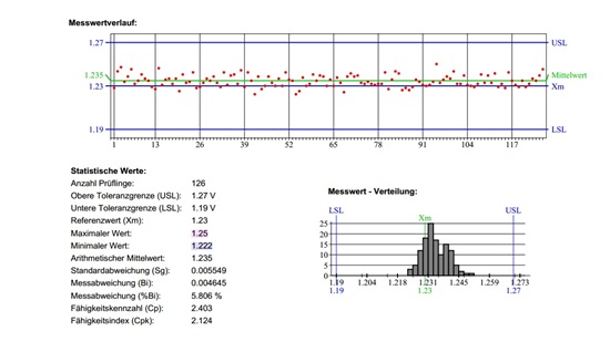
So here is the dispersion on the last batch on the voltage feeding the OFFSET pin mean value 1.235V, standard deviation of 5.5mV, i.e 0.44% of mean value.

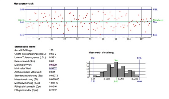
And then, here is the dispersion on the amplifier output, without any current in the shunt.


Now the mean value is 0.611V, and the standard dev is 20mV, i.e 3.2% of the mean value.

So the question is why there is such a dispersion on the offset on the output of the amplifier ? Any way to reduce it ?

Because if I want to fix the upper and lower limit of the measure not to reject good boards, it will be a tolerance of around 20%, a not acceptable range.

Hope to read some answer soon!!

Christophe

  • Christophe,

    I'm looking for that information presently and I (or someone else) will help you shortly.

    Thanks for using TI products!

    Best regards,

    Jason Bridgmon

  • Hi Cristophe,

    Looks like noise contribution.

    Have you taken the effects of noise into account? What is the Bandwidth of your measurement? Do you average or integrate? Do you have a filter on pins 3-4? Are you limiting the BW to only the range you need?

    Have you looked at the output with a scope, making sure averaging and any "filters" are off?

    The input referred 0.1-10Hz noise is 16.4uVpp. 16.4uV X 100 = 164uVpp of random noise at low (<10Hz) frequencies. Wideband noise (>10Hz) will be higher. Roughly about 1mVpp of additional broadband noise. Remember that the input noise and offset numbers are input-referred...and will be 100x worse at the output.

    Unfortunately, one of the side-effects of high-side current sense is the very poor signal/noise ratio due to having to level-shift using large value resistors, and having to amplify an already attenuated (noisy) signal. This is why a provision for a filter was included.

    A 2mOhm resistor tells me you are either looking to measure a very, very large current, or are using a very low value sense resistor to (understandably) reduce power dissipation & loss.

    You may need to increase the size of the sense resistor if noise is the issue.

    Regards,

  • Hello

    Thanks for the answer and technical details, but I think noise can not explain all, as the measurement of the output of the amplifier is implemented after an additional RC filter with 100ms time constant. There is also a 1nF filtering ceramic cap added between the two stages and the integration time of the functional test fixture is 20ms.

    And during the functional test I have also a measure of the output with a 1Amp current in the shunt, and there is the same distribution of the measure, i.e. if the measure of the output of the amplifier was near the low limit without current, it will be also lower with current. If it is a matter of random noise, it is strange that the two measures are correlated, isn't it ?

    And you are right, the design is tailored for large pulse currents up to more than 80Amps!

    Hope reading soon your feedback

    Regards