This thread has been locked.

If you have a related question, please click the "Ask a related question" button in the top right corner. The newly created question will be automatically linked to this question.

INA219 wrong bus voltage measurement with no input - always read some ~800mV value

Other Parts Discussed in Thread: INA219, TPS54395

Hello,

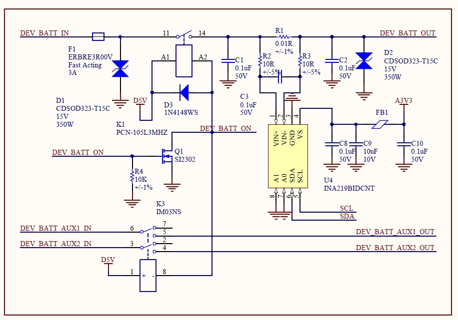
We have a board with three INA219 connected on the same bus (with diff addresses):

- schematic identical that in datasheet Page 9 (Typical Circuit)

- powered by analog LDO @ 3V3

- 10mOhm shunt, 10 ohms filter + // 100nF

- 100nF on each side of shunt to GND

- TVS (bi-dir, 15V) on each side of shunt to GND

- measure some lithium cell, max 5V

- The gain is 1 (40mV range) and we use 12 bit continuous.

Now everything is right, bus voltage reading is within 10mV accuracy of target. But with no inputs at all, we constant read some 800mV value.

If adding a resistor to GND on any input (100k for example) the reading decrease to 300mV. When lowering this value to 1k, almost no error voltage readout but this of course will false the current reading. If we measure externally, indeed, the voltage is there but from where? There is nothing on the measured line except schematic from datasheet.

Moreover, even the BUS voltage is correct, with absolute no load we still measure some 10...12mA from nowhere.

Software calibration doesn't help at all. Can you suggest what's happening?

Thanks for any suggestions,

  • Can you provide the schematic with the surrounding circuitry? I know you said "schematic identical that in datasheet Page 9 (Typical Circuit)" but it really does matter to see what is around it.

    The Vin- input has 320k to GND, which at 5V should only be 15uA additional current through the shunt and certainly 10-12mA. I've used the EVM and seen no such behavior - bus voltage is accurate and Vsense = 0, as expected. I assume you have done this already - have you verified with an ammeter that 10-12mA of current is not flowing from the voltage source to the inputs?

    Floating inputs are not an intended use case and we do not recommend it. Without bias, the front end of most (if not all) of our INA parts tend to drift to different levels of stability that we can't really simulate.
  • Hello Jason,

    There is nothing special in schematic :) Without any BATT (so line not connected) the INA219 reports 800mV and this voltage can actually be measured on BUS. The A3V3 is coming from MCP1700 which is a quite good LDO and power only the INA products. The I2C bus has 4k7 to D3V3, the same as for some Cortex M4, and is coming from some TPS54395.

    The board contains also a FT4232 chipset but with USB disconnected, the voltage is still present, so no ground loops from laptop, etc. Interesting, all 3 parts we have in design behave the same, few mV difference in reported voltage.

    If we bias the V+ or V- with 100k to GND, the readout is ~300mV so clearly, some thin currents involved here. I read from some other current monitor part (analog, I can't remember the part name) that output of OA (internally inside INA219) cannot swing bellow some dozens of mV on unipolar supply and this can appear at inputs.

    I need to understand the source of un-wanted voltage :)

    Thanks in advance.

  • It sounds really suspicious - have you tried replacing/removing the filter caps (C1 and C2 specifically, maybe C3)? I'm wondering if you might have a leaky cap.
  • Hi Jason,

    I removed all 3 caps and TVS, the same story. I changed the main board PSU (linear one) to another.
    I powered one INA219 from 5V bar and the residual voltage increased to 1V!

    If you have time and a demo board with INA219, with no connection other than shunt (and filter res, caps), please measure the BUS voltage with a DMM multimeter.

    Or my parts are defective but I ordered through Farnell which never sends us bad parts (or soldering, but this rarely happens).

  • Forgive me if I misunderstood, but could you confirm that you are connecting only a shunt resistor between the inputs and no other connection to a power or ground line on either input?
  • I don't understand "only one"... of course, like in schematic I posted, identical.

    We connected a 100k resistor to GND (from either VIN+ or VIN-) just to see what's happens (not figured in schematic).
    We discovered that this resistor will cancel somehow the voltage seen by INA219 but this is for test only.

    Like I said, the device measure BUS voltage just fine above that threshold, when we connect our battery under test, DMM (a 5 1/2 FLUKE) measure 4.175 and INA219 reports 4.186 which is just fine. In this case, reported current is still wrong, INA says 12mA but other side is un-connected to anything (no real current flow at all).
  • Alright, I think I understand. We can set up the EVM in the lab, though I'm on travel currently. I'll see if someone on our team can get to it today or tomorrow, otherwise I'll be back in next week.
  • I'm back in town so we'll get this set up shortly and continue investigation. Any updates on your end?
  • Hi,
    I benched INA219. Vs=3.3V, Vin+ and Vin – floating with no Rshunt. I measure Vin+ = ~920 mV and Vin- = ~800mv. This voltage goes up a little when I raise the supply to 5V. Did you have a Shunt Resistor tying both inputs when you connected battery under test with 4.175 V out?
  • This is the voltage I'm talking about !

    I have 0.01R shunt connected (see schematic in my previous post) but, as in your reported measurements, the V+ and V- voltages are quite the same @800mV so no matter shunt is connected or not, you should measure the same voltage in respect to GND. Exactly what we measured, when powered @5V, this voltage increased a bit. Yes, the battery was a LiIon with about 4.2V.

    From INA219's datasheet first page "The INA219 senses across shunts on buses that can vary from 0V to 26V" and I really cannot see how it can measure under 1V since residual voltage will mask measurements.

    In our case this is not a problem because we can make a software threshold to dump values under 1V but can it be fixed somehow?

    Best regards,

  • Hi,
    I verified at Vcm < 1 V INA219 reads the correct Vbus and Vsense (Voltage between Vin+ and Vin-) voltage. If you connect one end of the input to supply and leave the other input floating then you may not read zero current depending on where the other inputs floats up to. Is it possible for you to disconnect everything connected to the input and only connect 1 V supply to Vin+ and either short Vin+ to Vin- or connect them through a sense resistor and see if your Vbus and Vsense readings are correct. Can you please share your register readings as well.
  • Dear Rabab,

    I'm NOT speaking about Vcm < 1V. This is Vbus < 1V we have troubles. I think parameter

    Bus Voltage (Input Voltage) Range          0....16V and 0....32V

    should be modified in datasheet to specify there is a residual voltage ~800mV (due to rail?) that appears on Vbus (...)

    Probably a slightly negative supply voltage in respect to Vbus will solve the measurements.

    Anyhow, thank you very much Jason, Rabab