This thread has been locked.

If you have a related question, please click the "Ask a related question" button in the top right corner. The newly created question will be automatically linked to this question.

INA240: How can inline CMM drop across shunt ever rise to 80v +/- inputs limit if VS is completely isolated from input CMM?

Guru 54077 points
Part Number: INA240
Other Parts Discussed in Thread: INA282, , INA301, DRV8305

Can TI lab please confirm (inline) shunt monitor 9.2.1 is possible up to 200v maximum. Is not the inline phase voltage CMM completely isolated from VS supply voltage and output pin 8?

It seems the drop across a inline shunt would never rise more than several hundred millivolt same as low side current monitoring. That said even if a motors phase voltage exceeds 80v there should be no current path into VS/OUT from IN+/- or have I missed something here?

The 80v limit seems realistic for a high side monitor where IN+ might connect to B+ and the entire shunt exists before MOSFET drains. This 80v maximum seems less relative when entire shunt exists inline phase mode. Point is there seems should be no path for shunt drop voltage to enter B+ or visa versa since IN+/- exist above ground or B+ but never encounter both sides at the same time inline with a BLDC. 

We have used the INA282 up to 190v supply for low side monitors and now INA240 similar case but have discovered a pesky flyback getting into analog data through low side INA240 monitors.

  • The abs max for the INA240 for common mode voltage is 90V.  The part is not an isolated part, though the front end and Vs are powered separately.  The ground is common for both.  Low side of 190V is not an issue because the common mode is basically 0, as you know.

    Am I understanding correctly that the flyback is present with the INA240 but not the INA282?  I've been looking at your scope captures on the other thread and there are certainly dips present in the output, but I'm not sure what is causing them.  I'll see about getting something set up in the lab to investigate further.

    Another recently released option that could work for low-side motor current measurement is the INA301.  I initially didn't think to recommend it because I thought you were primarily seeking in-line current measurement.

  • Hi Jason,

    Jason Bridgmon said:
    The abs max for the INA240 for common mode voltage is 90V.

    Have to wonder how common mode is an issue if the front end is powered separately other than sharing ground. It seems to me the drop across the shunt is subtracted from phase B+ or added to GND during any given bipolar switch time since the inline phase floats near mid supply in trapezoidal wave forms. An Idle mode phase has about 10v leakage to ground even at 190v yet 0v leakage across any two phases in a Delta or WYE.

    Jason Bridgmon said:
    Am I understanding correctly that the flyback is present with the INA240 but not the INA282

    The INA240 makes it clear a some sort of PWM flyback voltage across shunt was/is plaguing the current monitor ADC system. The INA240 signal output is more defined and strips out most the low level pulses cross talk occurring from the copartner phase and present on all the IAN282 captures.

    The INA240 scope shows a single set of flyback PWM pulses moving back and forth across the ratio metric liner current rises. So when pulses leave one rise the one it left looks really clean and flyback burst is bopping all over from peak to peak in no specific order.  I doubled high side B+ electrolytic (470uf to 940uf) and that cut high side +24vdc flyback PWM (+/-4v) peaks in half but did very little for the low side they infect.


  • Jason Bridgmon said:
    Am I understanding correctly that the flyback is present with the INA240 but not the INA282?

    Hi Jason,

    Fairchild forum post calls flyback pulses, FET switch node spikes. Did some more testing to determine if something in software was causing PWM spikes and shortened dead time but nothing stopped these spikes so far. Also added 1nf cap across VIN+/- and twisted with ground the signal pair cables out of each INA240 shunt PCB. 

    The inverter high side +24-160vdc have expensive snubber capacitors, poly pulse cap 0.22uf parallel and 470uf @1.9amp ripple current. So these spike pulses seem quite normal. Slowing down the high side FET is not an option as switching is already fairly slow at 12.5Khz PWM, efficiency loss results. Think ON Semi link is more relative to 100Khz or above PWM.

    Oddly when I zoom in on scope horizontal time base these PWM spikes 240 output are part of current measure in each FET on time, show as ringing pulses.

    FYI: https://community.fairchildsemi.com/thread/1032

    0.22uf Poly snubber:

    /cfs-file/__key/communityserver-discussions-components-files/14/2772.Capacitpr-CDE-600v-snubber-pulse-metal-film-940C.pdf

    High quality 470uf electrolytic:

    /cfs-file/__key/communityserver-discussions-components-files/14/0638.Capacitor-electrolytic-Nichicon-CY_2D00_CL-series.pdf

  • Hi Jason,

    Jason Bridgmon said:
    I've been looking at your scope captures on the other thread and there are certainly dips present in the output, but I'm not sure what is causing them

    Now have reference inputs configured REF/2 and we get +1.65v INA240 output level same resistive divider now sets 690mv signal ADC floor versus 0v. The 240 output signal should indicate symmetrical +/- current directions and the load is reflective of the low side +IN CMM facing supply and -IN CMM facing ground.

    All seems fine with reverse current measures (GND to B+) yet what appears to be forward current is not being measured in monotonic voltage ramp like the reverse current. Some engineers seem to call that behavior a linear ratio metric output level. Otherwise the INA240 has not identified the direction of current flow across the shunt in the datasheet as being either reverse or forward and both directions do technically exist.

    Perhaps forward current is not always a concern in low side monitors as it seems to originate in FET body diodes snubbing inductive kick back to ground or B+ respectively. Or it is reverse current regenerative in nature, the motor acting as a generator producing it's own current directed back to battery. Either way TI motor driver engineers claim similar low side circuits can measure +/- current in the full shunt voltage scale. Source DRV8305 current sense amplifiers section 8.2.2.4 and sense circuit illustration Figure 12.  

    Is there some reason why 240 bidirectional mode produces a monotonic voltage ramp in one current direction and not the other? Or is INA240 thus missing that AC ratio current information when not being inline phase monitor?

  • Scope RF1&3 are INA282 low side 18m shunt: Both 1/2 cycles current flow are measured when 282 was configured REF/2. INN faces GND and INP faces the load, Reversing shunt polarity reverses the output signal. 

  • Hi Jason,

    Jason Bridgmon said:
    The abs max for the INA240 for common mode voltage is 90V.

    The INA240 datasheet 7.1 AMR shows analog inputs have differential  (-80v to +80v). That seems the INA240/282 are 160V bipolar devices and not simply having an -4 to 80v CMM as the datasheet description 3 suggests.

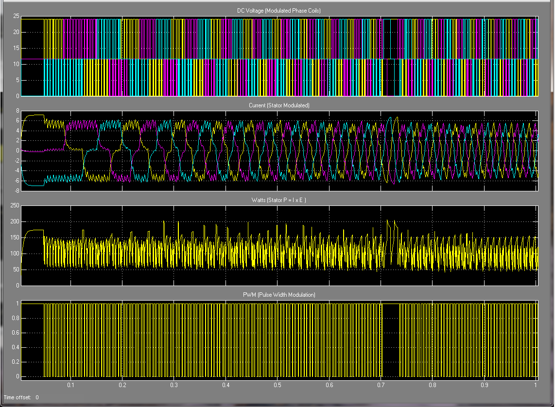
    A TI forum engineer some time ago explained the inverter is bipolar even though it is powered from a single ended battery source. Matlab seems to concur with that engineers assessment and the PWM inverter produces a Bipolar output crossing 0 volts therefore reflects an AC battery source signal output. That is not common mode it is bipolar. In my opinion the vendor should properly test the INA devices in a bipolar inverter and show both the CMM and Bipolar maximum in this case.

    Have to wonder if the INA240/282 AMR -80v has been tested in the presence of +80v bipolar voltage swings??

    A capture of the inductive current produced in a bipolar inverter powered from a singled ended power supply.