Hi Team,
The customer is using INA226 to detect the current, the voltage, the bus voltage and the power. The 00h register value is set 4093 (hex).
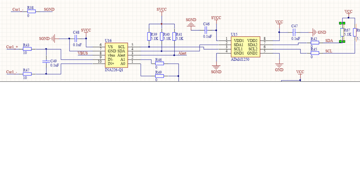
The 05h register value is set 06AB (hex). The attachment is his schematic and code. For the schematic, A0 pin and A1 pin is short to GND.
The external circuit input the current to the input pins of INA226.
The issues are as the belows:
1: The customer cannot read the current, the voltage, the bus voltage and the power value at the same time. But he can read any value of these parameters
separately. The result of the reading is different from the actual test value.
2. For the 00h register and the 05h register cannot be read at the same time. If the customer reads the 00h register, the 05h register value is 0.
the customer reads the 05h register, the 00h register value is 0.
3. Even if the customer connects the IN+ pin to the IN- pin, the result of the reading is FF.
Q1: For the customer's schematic and the register configuration, are these correct? If they have problems, how to modify the schematic and
the register configuration. Please give me a correct step to configure the registers. Does the customer refer to the Table 1 Calculating Current and Power
for the register configuration?
Q2: I think the customer the input signals are the current for the IN+/- pins. But I think the input signal is the voltage for the IN+/- pins.
Is my understanding correct?
I would like to verify the input voltage range of the IN+/- pins.
What is the Shunt voltage input range of 6.5 Electrical Characteristics for the datasheet?
Best Wishes,
Mickey Zhang
Asia Customer Support Center
Texas Instruments


