This thread has been locked.

If you have a related question, please click the "Ask a related question" button in the top right corner. The newly created question will be automatically linked to this question.

INA193: INA193 about the output voltage issue

Part Number: INA193
Other Parts Discussed in Thread: INA169, INA240

Hi Team,

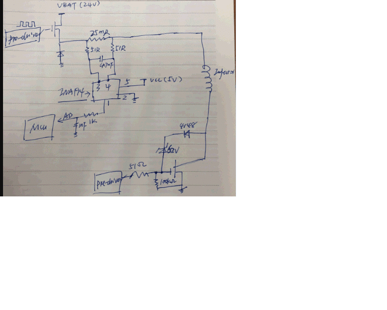
The customer is using INA193.  The customer refers to the Figure 23 to design his schematic. The schematic is in the attach.

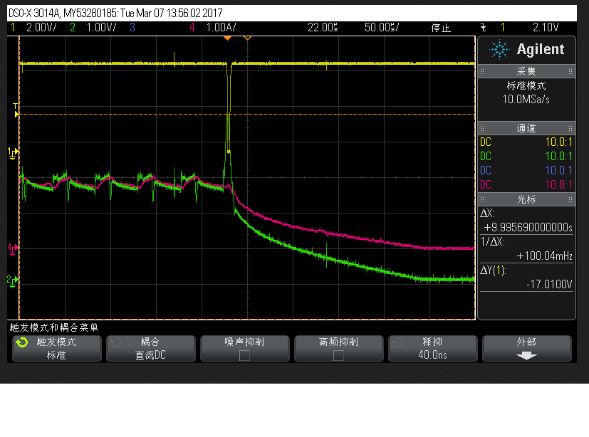
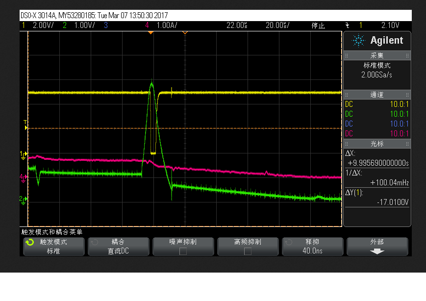
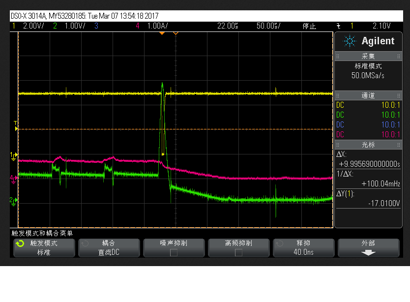
Sometimes, the output voltage reaches 5V. This will cause the system to erroneously determine the load overcurrent.

Q1: Is the customer's  schematic correct? 

Q2: How to solve the issue?

Q3: For INA193, if the customer would like to detect the load current, how to determine the RSHUNT value and how to calculate the load current

through the output voltage value ,the RSHUNT value and the GAIN?

There is a my previous post: 

For the INA169 example, do we want to detect a 20A load current ? If we want to  detect a 20A load current,

why are the RSHUNT value determine 10mohm and set the GAIN 20V/V? How to calculate the load current through the RSHUNT value and the GAIN value?

Best Wishes,
Mickey Zhang
Asia Customer Support Center
Texas Instruments

  • Hi Mickey,

    I will start clarifying that the INA193 and INA169 are two different types of current shunt monitors. The INA193 is a voltage output current shunt monitor and the Gain is Set inside the device. The INA169 is a current output current shunt monitor and the gain is set by the user using an external resistor in the output.

    The INA193 have a gain of 20 V/V. The customer need to select the shunt resistor based on the load current he wants to monitor. The following tutorial video will provide you and your customer with all the information and equations needed to learn how to select the Rshunt value for the application: training.ti.com/getting-started-current-sense-amplifiers-session-4-how-choose-appropriate-shunt-resistor
    I am not sure what is his min/max load current so won't be able to recommend a shunt resistor value at this moment. Please have the customer review this video and let me know if you needed further support.

    In the INA169 example from previous post the shunt value and gain were selected just for illustration purposes. To show you how a current output device works. Vout = (ILoad*Rshunt* Rload) / 1kohm

    Please refer to INA169 datasheet feature description and application section for an explanation of how the INA169 works. The datasheet explains the relationship between shunt resistor, vshunt, Gain setting Resistor (Rload) and voltage range limitations.

    You can find more training material in the following link: https://training.ti.com/getting-started-current-sense-amplifiers

  • Hi Mayrim,

    For the customer's issue, can you give some suggestions?

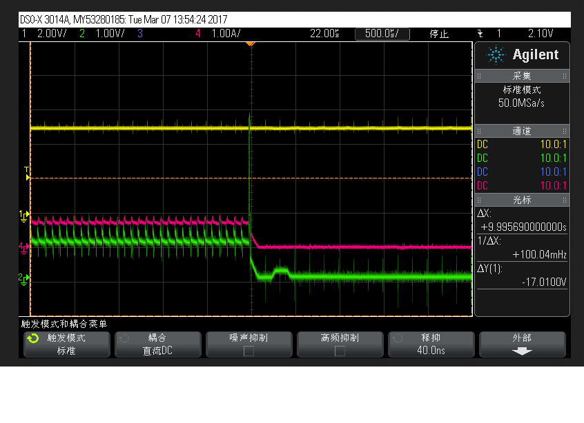
    There are four waveforms for the issue. The green waveform is the INA193 output voltage. The red waveform is the load current. The yellow waveform is

    the post-level comparator output voltage.

  • Hi Mickey,

    I have a few questions, please see below:

    1. Where are you measuring the Vout (Green Trace in your plots)? At Pin 1 or across the 1uF filter capacitor?
    2. It seems like depending on which switch is ON the Vcm (Common Mode Voltage) will have a large variation. Any tolerances errors between the series 51 ohm resistors will create common mode errors as well. I would recommend to eliminate the input filter for debugging. Remove the 4.7nF cap and replace the 51 ohm resistors with 0 ohms resistors. Please send us new scope shots if you see any changes after eliminating the filter.
    3. I would like to simulate the circuit in TINA for better understanding of the circuit. Can you please let us know what is the ON/OFF timing on the 2 FETs?

    Regards,

  • OK. I will confirm with the customer. The waveforms are measured by the customer. At Pin 1 or across the 1nF filter capacitor.

    I think this case looks like another case: e2e.ti.com/.../496135

    Can I recommend INA240 to repalce INA193?
  • Hi Mickey,

    Please confirm with the customer if replacing the 51 ohm resistors with shorts help. I agree, that issue you found in the forums seems very similar. If the problem is the changes in common mode I also believe the INA240 will be a good device recommendation. The INA240 provides high levels of suppression for large common-mode transients.
  • Hi Mayrim,

    OK. Thanks for your reply. I will confirm with the customer.