This thread has been locked.

If you have a related question, please click the "Ask a related question" button in the top right corner. The newly created question will be automatically linked to this question.

INA271A-Q1: Vs Vsense and Vout connect

Part Number: INA271A-Q1
Other Parts Discussed in Thread: INA271, OPA192-Q1, INA188, OPA191, OPA192

Hi,

Now I am using INA271A-Q1 for current sensing to get the input current of buck devices'. We want to get accurate input current @Vin=4.5V-28V, Vout=1.05V-7V, Iout=1mA-8A. When the application condition is Iout=1mA, the input current is very hard to get accurately measured. So we want to use a current sense and we find INA271A-Q1, but when designing, I have the following confused:

1. Above is our schematic. J1-J2 is the power supply input, from 4.5V-28V. The current through R1(Rsense=0.1ohm) will be from 1mA to 8A for my application. So the question is: can INA271A-Q1 support this wide current range sense?

2. Because I see that Abs max of Vo= Vs+0.3V. In my application, when Vin=4.5V, Isense=8A, Rsense=0.1ohm, Gain=20, we can get Vo=16V which is larger than Vo abs max. Do I calculate right?

3. What is the meaning of section 9.1.2 selecting Rs? the following means we would better make the Vsense between 50mV to 100mV? Or Vo between 50mV to 100mV?

For most applications, best performance is attained with an RS value that provides a full-scale shunt

voltage range of 50 mV to 100 mV. Maximum input voltage for accurate measurements is (VS – 0.2)/Gain.

4. if Item 3 is true, when my application is 1mA loading, we can only get Vsense=1mA*0.1ohm=0.1mV, Vout=2mV. Can part work well at this situation?

5. if this part can't support my application, would you mind to recommend another part?

  • Hi Sara,

    Thank you for your query,

    Its always hard to determine whenever such a high current range will be supported. A few factors to consider...

    • How accurate should it be?
    • What's the allowable voltage drop on the circuit? (AKA,  required output voltage regulation)
    • What are the allowable losses on the sense resistor?
    • What is the precision of the ADC to be interfaced with this part?
    • Shall the device measure down to 1mA and up to 8A or do you only require it to survive transients of such amplitude?

    Now lets go to the math side of things...

    • You specify a voltage input of 4.5 - 28V - The part worst case quiescent current is close to 900uA, the 5K input resistor will dictate a minimum input voltage of 9.5V, neglecting any output current from the INA271. I would revise this section of the circuit.
      • The maximum input voltage, at a current flow of 8000mA Through a 100mR resistor is 800mV
      • The sense resistor must be capable of dissipating 6.4W in thermal energy.

    • You required resolution is about 8000 steps, given by dividing the largest input value by the smallest input value, hence 8000mA/1mA = 8000.
    • This will require a 16bit ADC, because a 12bit ADC can only measure a total of 4096 different Values (2^12)
    • The correct statment is Vo = (VS-0.2), therefore for a 4.5V supply voltage, the maximun measurable sense voltage would be 215mV or 2.15A
    • The minimum input voltage, at a current flow of 1mA, through a 100mR resistor is 100uV. This goes with question number 4.
      • The device specs a worst case scenario offset of 2.5mV, plus 20uV/°C, essentially anything lower than 25mA cannot be accurately measured
      • Similarly, Vsense values below 20mV can be measured but result in an accuracy degradation which TI can't quantify. Would you be able to advise the required accuracy for your application?

    I will need a few more details from you before I can make a recommendation on a suitable part. I will most likely not be able to recommend anything that can accurately measure down to 1/8000 resolution, but if you could specify the required current ranges and allowable error range along with the maximum current the device is required to survive, I can certainly look into a few more solutions and advise.

  • Hi Carlos,

    Really appreciate for your reply.

    My application is only to measure the input current. Through measuring the Vo of IN271, we can get the Vsense by divide Gain, and then we can get the input current. The reason why we use current sense part is that when the input current is below 10mA, we can’t get the accurate Vsense without a gain. So we don’t need connect Vo to an ADC, we just connect the Vo to a multimeter to measure its voltage.

    • How accurate should it be?

    • +-5% is okay. For example, when the input current is 1mA, Rsense=0.1ohm, Gain=20, so the Vo=2mV. We can accept the Vo from 1.9mV to 2.1mV.

    • What's the allowable voltage drop on the circuit? (AKA,  required output voltage regulation)

    • Same as above.

    • What are the allowable losses on the sense resistor?

    • We used 0.1ohm resister’s power rating @25C is 30W.

    • What is the precision of the ADC to be interfaced with this part?

    • We don’t need the ADC.

    • Shall the device measure down to 1mA and up to 8A or do you only require it to survive transients of such amplitude?

    • Actually, we need to sweep from 1mA, 2mA…10mA, 20mA…100mA, 200mA…1A, 2A…8A each points to measure the Buck device’s efficiency. So we need to get the input current accurate.  But if the current sense part can’t support the resolution, we can only consider the situation that the input current is from 1mA to 1A. Because we can get the current without a gain (Current sense) when input current above 1A.

    • You specify a voltage input of 4.5 - 28V - The part worst case quiescent current is close to 900uA, the 5K input resistor will dictate a minimum input voltage of 9.5V, neglecting any output current from the INA271. I would revise this section of the circuit.

    o The maximum input voltage, at a current flow of 8000mA Through a 100mR resistor is 800mV

    o The sense resistor must be capable of dissipating 6.4W in thermal energy.

    o And what about change the 5K input resistor to 50K. For the input of 4.5V-28V, the current is from 90uA-560uA with 50K resistor. Right? I think the 0.1ohm sense resistor which power rating is 30W can handle the 6.4W dissipating and also the sense resistor has a thermal pad.

    • The minimum input voltage, at a current flow of 1mA, through a 100mR resistor is 100uV. This goes with question number 4.

    o The device specs a worst case scenario offset of 2.5mV, plus 20uV/°C, essentially anything lower than 25mA cannot be accurately measured

    o Similarly, Vsense values below 20mV can be measured but result in an accuracy degradation which TI can't quantify. Would you be able to advise the required accuracy for your application?

    o For this feature, I really pay attention to the lower 1mA. You mean this part can’t be accurately measured when the current lower than 25mA which does not match with my application. So would you mind to recommend a part that can handle the lower current 1mA-1A with a 100mR sensen resistor?

    Appreciate for your reply.

  • Hi Sara,

    Thank you for providing additional information regarding this matter.
    I am looking into what better options to advise and should get back to you soon. Thank you for your patience on this matter.
  • I believe your best option for currents that low is to go with an op-amp. I strongly advise on a negative bias supply rather than simply relying on a rail to rail variant, to keep offset and linearity as good as possible when measuring the small currents. I will move this thread so that my colleagues can assist you.

    As to your comment above, I don't believe you correctly understood my point regarding the 5K input resistor. This is R2, the series resistor that, together with the zenner diode, forms the voltage regulator circuit that powers up the device. This resistor value should be lowered to accommodate the required operating current at lower input voltages while also supplying the minimum required reverse current for the zenner to regulate.

  • Hi,

    Thanks.
    Any updates for the recommendation part?
  • Hi Sara,
    I will get back to you tomorrow regarding this one, will have to discuss with the team.
    Thank you for your patience on this matter.
  • Hello Sara,

    Your inquiry has been shared with us in Precision Amplifiers to see if we could propose a possible solution.

    Conceptually, some of our recent precision op amp releases that can operate with the required supply range of  4.5 V to 28 V, and have an input common-mode voltage range from supply rail to supply rail might provide a solution. The one device that has the necessary properties and is AEC-100 qualified, is the OPA192-Q1. It is a low-noise, low-offset, high-performance op amp that has the necessary rail-to-rail common-mode voltage range needed for this application. Note that the datasheet is marked "Advanced Information" so you would have to check on its availability.

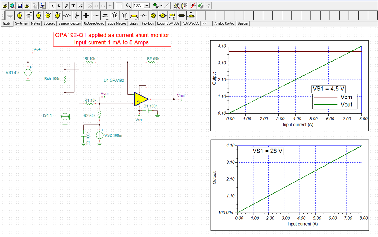
    Below, I show the current-shunt monitor concept for a range of 1 mA to 8 Amperes with a 100 Milliohm shunt resistor. The gain is set to 6 V/V becuase the output would hit the high upper rail if the drop across the shunt resistor were any greater with 8 Amps of current. This really limits the resolution at the very low current end of 1 mA. Also, since the OPA192-Q1 output cannot go all the way to zero, a small 100 mV common-mode voltage is added to the non-inverting input to keep the output off the lower rail. This portion of the circuit would have to be further refined.

    Regards, Thomas

    Precision Amplifiers Applications Engineering

  • Sara,

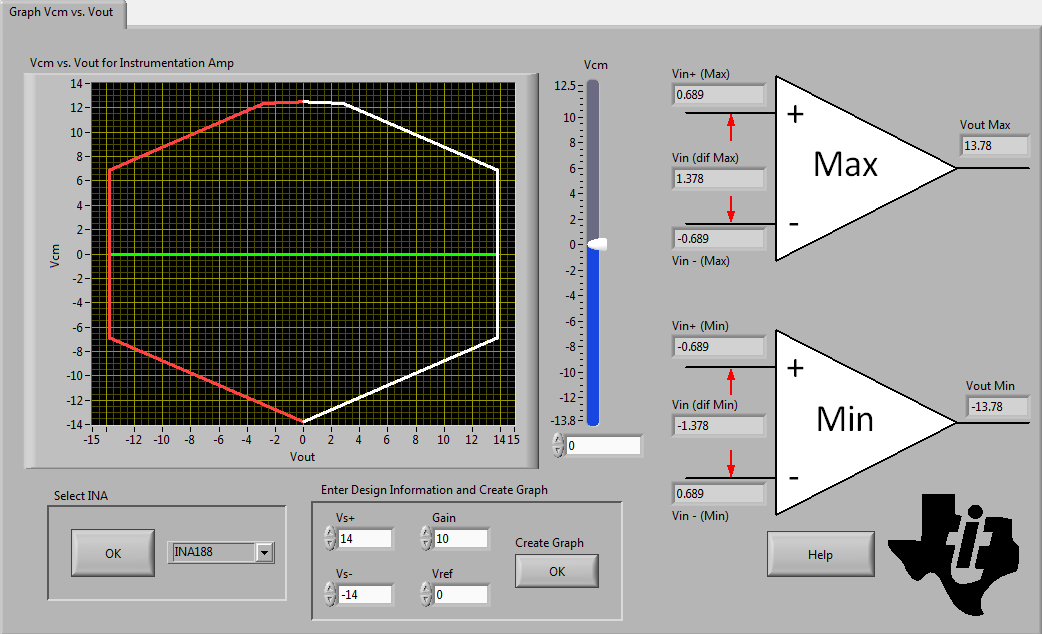
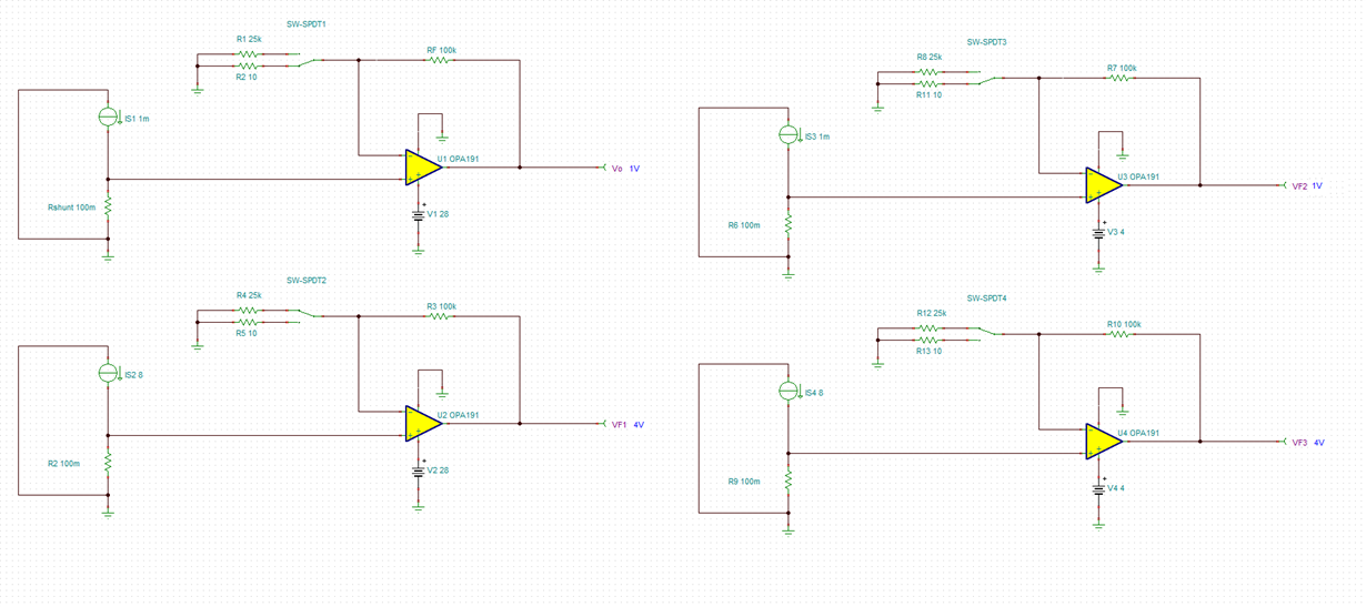
    You could potentailly use our zero-drift INA188 instrumentation amplifier (max Vos of 55uV since you try to measure 100uV sense voltage for Iout of 1mA) but this would require you to use dual supply, +/-2V < Vsupply <+/-14V, since the input common-mode and output voltage range does not reach the negative rail.  

    Also, since you attempt to measure four decades variation in Vsense input range, you would have to switch the gain resistor to adjust the output range to the input range of  100uV < Vsense < 800mV.  For example, gain of 5 for Ishunt of 8A (Vout of 4V) and gain of 10,000 for Ish=1mA (Vout of 1V) - see below:

    But the simpliest solution would entail using one of our precision op maps, like OPA191, and use a switch at certain Ishunt level to change the gain - see below:

  • hi,

    Thanks for your detailed reply.

    Would you mind to check whether the following SCH is Okay?

    What I really want is the voltage difference between the two terminal of Resistor R1. So I want the connect OPA191 Pin 3 with VIN voltage instead of GND.

    Really appreciate for your apply.

  • Hi Thomas,

    Thanks for your reply.
    I am confused with the 100mV common mode voltage added. Is it okay if we don't add it? Why we should add it? Because the OPA192's spec limited? Which spec limit this?

    Thanks for your reply.
  • A very small or zero differential input voltage will drive the output of a difference amplifier to a voltage where reference voltage is connected to - VS2 in the schematic above.  Since the output of OPA192 cannot swing all the way to negative rail, you must reference VS2 to a voltage that output get reach; ~100mV in the case of OPA192 for RL>10kohm - see below.

  • Sara,

    You cannot measure high-side current with a single op amp and reference the output to a negative rail - it simply will not work.

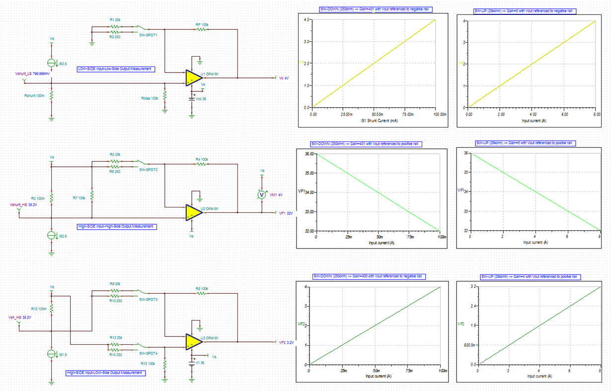
    Below please find three different methods that will work for your 1mA to 8A input current across 0.1ohm shunt resistor but this will require a change of gains at around 100mA level. For that reason, I have changed the resistor values to accomodate new gains.  In order to lift the output away from the rail, the minimum gain for 1mA shunt current was set to 400 which assures the output being at least 40mV away from either rail (linear output swing).

    The first circuit measure low-side current with the output referenced to negative rail.  The second circuit measures high-side current with output referenced to positve rail.  And the third one measures high side current with the output referenced to negative rail. 

    I have also attached circuit schematic so you may use for your own simulations.

    OPA191 Sara current shunt.TSC

  • Hi Marek,

    Really thanks for your reply.

    I also have a question here:

    The third one measures high side current with the output referenced to negative rail which is the same with my SCH as post before (As below) except the Gain seting of R3 and R5. Am I right or what have I missed?

  • Sara,

    Yes, that's correct.  For the circuit to work properly on 4.5V supply, you need to lower the first gain to maximum 400 (250ohm) so for 100mA shunt current, Ishunt, the output goes to 4V.  The way it is now, the output would become non-linear around 4.5mA for 4.5V supply and 36mA for 36V supply - see below.

  • Marek,

    Okay, got it.

    Really thanks.