This thread has been locked.

If you have a related question, please click the "Ask a related question" button in the top right corner. The newly created question will be automatically linked to this question.

INA240: DC motor current sensing to check if the motor is stuck using either INA240 or INA181

Part Number: INA240
Other Parts Discussed in Thread: INA181, INA139

Hi,

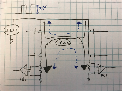
I design an application to drive a DC motor using an H-bridge and a PWM to set the speed.

My main concern is to know if a motor is stuck, I do not want to do it using my speed sensing block as it has other uses.

I would like to sense the current and understand when access current is drawn.

My max voltage is 30V drawn from the battery. average voltage is 18V (using the PWM), average current is about 10A.

From looking through the parts I see two options:

1. The INA240 for inline current sensing.

2. INA181 for high/ low side current sensing.

My questions are:

The motor will run in both directions so I will need a bidirectional current sensing if I will use the inline method.

suppose Vref=1.5V and VS=3V,

Using the INA240 will I Vout between 0 to 3V? 1.5 to 3 for one direction and 0 to 1.5 for the other direction?

Using the INA181 - where would it be better used? Low side or High side?

Please correct me if I am wrong but here I do not need bidirectional sensing as the current seen by the shunt resistor will always be in one direction no matter what the motor direction is right?

What is your recommendation for the best part for this specific application?

Remember that I just need to understand if the motor is stuck, i.e. excess current.

Thanks,

Tomer

  • Hello Tomer,

    I am working with our expert now for your scenario. Will get back to you soon.

    Peter Iliya
    Current Sense Applications
  • Hey Tomer,


    If using the INA240, I assume your schematic to approximately look like the following:


    To answer your questions, the INA240 output would be 1.5V to 3V for one direction and 0 to 1.5V for the other direction. These are ideal output swings to the rail and in reality they would be limited by the device’s output stage. You can read more about this here in our FAQ page.


    If using the INA181, I assume your schematic to approximately look like the one below in a low-side configuration with two INA181 devices to detect excess current (stuck motor) in both motor directions.


    Note the INA181 has an absolute/recommended maximum common-mode input (Vcm) of 26V, thus you cannot use this device in the high-side configuration because the PWM signal coming in would hit a peak of 30V. According to a search of our analog output parts sorted by price, the next cheapest part that could accept a Vcm =30V, is the INA139. Also, if you desire to know the current from back EMF during active braking (blue dotted lines), then you would not be able to see the top blue current line with a low-side configuration. Although this should not be a problem since the motor can’t really get stuck if it is already being braked.


    Comparing the INA181 and INA240 you would need a slightly larger shunt resistor with the INA181 since it has a larger input offset (150uV max), but you could reference both INA181 devices to ground since you will only care to sense a positive excess current in either motor direction. This will allow for greater dynamic range. The INA181 also has greater output current drive than the INA240.


    What is the PWM frequency? The INA240 has a 400 kHz BW and the INA181A1 (gain = 200) has BW of 100kHz. You will want to consider how much switching noise your system can tolerate. The INA139 does have a much higher BW comparatively.


    Please let me know if you have more questions.


    Peter Iliya

    Current Sense Applications

  • Hi Peter,

    Thank you for that.

    You are correct about the INA240 configuration.

    For the low side INA181 I was thinking something like this:

    Is it possible?

    That way i can use just one INA181.

    As for the PWM frequency it will be no more than 20Khz, will the INA181 be good for that?

    As a general question, what is the relation between the PWM frequency and the device BW? how do I know if a certain device can handle the PWM at a certain frequency correctly.

    Thanks,

    Tomer

  • Hey Tomer,

    What you have drawn would be acceptable and the INA181 could defintely respond with 20kHz PWM, granted that the duty cycle is not too low.

    For your other question there is no general rule of thumb for the BW needed to handle a PWM signal except that it should be larger than the PWM's frequency. The reason is that there are other significant factors especially for quickly-changing square waves. These include settling time, slew rate, CMRR, distortion, and device topology and these can be related to each other. I mention device topology because the INA240 is a chopping amplifier and the INA181 is a linear amplifier. Generally, while chopping amplifiers have lower offset and 1/f noise (for op-amps), they will usually be slower or create more distortion than linear amplifiers.

    Overall, I would recommend the INA181 for your applications.

    Peter Iliya
    Current Sense Applications
  • Thank you Peter,

    This is most helpful.

    Tomer