This thread has been locked.

If you have a related question, please click the "Ask a related question" button in the top right corner. The newly created question will be automatically linked to this question.

INA3221: Current sensing accuracy under different VIN+/VIN- voltage

Part Number: INA3221
Other Parts Discussed in Thread: INA219, INA226, INA230, INA220, INA231

Hi, team,

I have one question about INA3221.

What is the accuracy under different VIN+/VIN- voltage? For example, when VIN+/VIN- is 0~5mV, 5~10mV, >10mV.

Is this just influenced by the same offset, 1-LSB step error and gain error?

Thanks.

Johnny

  • Hello Johnny,

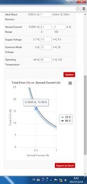
    I assume you are referring to the input differential voltage between VIn+ and Vin-. The accuracy of the device will only get better as this differential Vin input increases. You can use the online error tool located on right-hand side of the product folder page to see the Maximum RSS Error for differing Vin. According to the graph at 5mV you will get an error 1.62%.

    The error induced by input offset (Vos) and gain error are constant throughout the possible range of Vin. Some error sources will change as Vin changes: input bias current (Ib) increase as Vidff and Vcm increases. Vos due to CMRR will increase as Vcm increases. Overall though as the Vin gets smaller, these error sources become a larger percentage of the Vin signal and thus error increases.

    Sincerely,

    Peter Iliya

    Current Sense Applications

  • Peter,

    Thanks for reply. So the error 1.62% @5mV is only RSS error. We should take Vos and others into total error consideration.

    Do you have some accurate calculation result or test result about the total typical and maximum error under different VIN+/VIN-?

    Thanks.

    Johnny

  • Johnny,

    Vos, CMR, and gain error are taken into account already with the 1.62% value. This is the maximum RSS (root sum square) error value the customer should expect at 5mV differential input, 12V common mode, 25C temperature. RSS is calculated by determing the individual error percentages from each error source (Vos, CMR, gain error, Vos drift), summing the squares of these values, and then taking the square root of the total value.

    RSS = sqrt( e_Vos^2 + e_CMR^2 + e_GE^2 + e_drift^2)

    Are you asking for how to calculate error for different sense voltages (differential voltage to the inputs) or for different common mode values? You could just simply refer to the tool for this.

    Peter Iliya

    Current Sense Applications

  • Peter,

    Thanks for reply. I have another question.

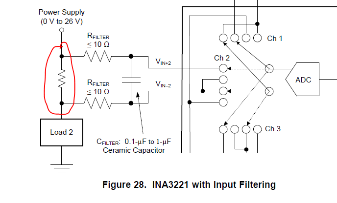
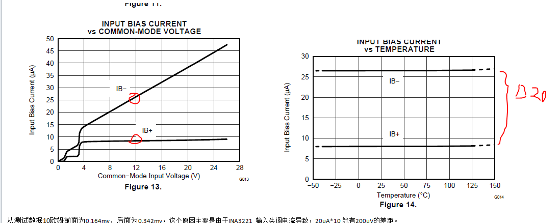
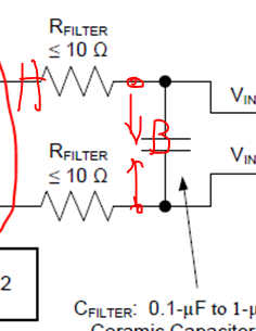
    Will below IB+/IB- bias current difference 20uA generate a 200uV voltage drop on 10ohm resistor?

    Thanks.

    Johnny

  • Hey Johnny,

    This is correct, but the INA3221 input bias current behavior differs from many of our other amplifier because of an internal 670kOhm resistor at the VIN- pin used to measure the bus voltage. This is why the Ib- curve increases while the Ib+ curve stays flat and the common mode increases. So there are two ways you can calculate the offset induced by IB (including the 10Ohm filter resistors).

    Method 1: Go to Ib vc Vcm and/or the Ib vs. Vdiff curve

    Vsense = voltage the device is sensing at input pins

    Vsense = (Rshunt*Ib-) - Ios*Rf;  where Ios = Ib+ - Ib-

    Vsense = (Rshunt*26uA ) - (8uA - 26uA)*10Ohms =

    Vsense = 26uA*Rshunt + 180uV

    Method 2: Use Ib values from parametric table and calculate with 670kOhm internal resistance

    This calculation is derived and explained here in our article for the INA3221 and INA219 products which have this internal resistance (Rin-):

    Vsense = -Ib+*Rf + (Rshunt + Rf)*(Vbus/Rin- + Ib-)

    Vsense = -10uA*10Ohm + (Rsh + 10Ohms)*(12V/670KOhms + 10uA)

    Vsense = -100uV + 280uV + Rsh*28uA

    Vsense = 28uA*Rshunt + 180uV


    You approximately get the same -180uV offset (due to the resistors) in both cases. This offset will add onto the initial offset (Vos) of the part +-40uV typical for a total possible offset of +220uV. A full error analysis will need to include the offsets from CMR (common mode rejection), drift from temperature changes, and gain error.

    Best,

    Peter Iliya

    Current Sense Applications


  • Peter,

    Thanks for reply.
    Is it okay to use one 10ohm and one 5ohm resistor to decrease this error?

    Johnny
  • Johnny,

    I would say this is reasonable as long as the bus voltage (or common mode voltage of the part) is not changing during when shunt measurements are needed. Additionally, the fc of the filter will increase ~3kHz so the effectiveness of the filter will overall decrease.

    One other alternative could be placing a shunt 670kOhm resistors to ground off the Vin+ input to balance out the Ib+ and Ib- currents, although using the 10Ohm/5Ohm filter does seem more practical if customer needs a filter anyway. This is shown in the article I've already posted: e2e.ti.com/.../3576.ina219-ina3221-input-impedance

    Another alternative is to use a substitue part without this internal 670kOhm resistor, but still measures VBUS. Then customer could filter with two 10 Ohm resistors. These alternative devices are: INA220, INA226, INA230 and INA231.

    Best Regards,
    Peter Iliya
    Current Sense Applications
  • Peter,

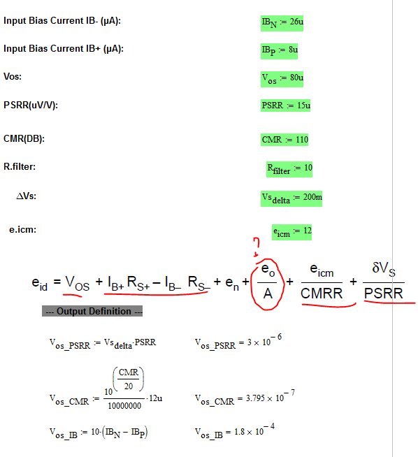
    Could you please help check wheteher below calculation is right or not?

    My questions:

    1. What is eo/A in above calculation?

    2. For RSS = sqrt( e_Vos^2 + e_CMR^2 + e_GE^2 + e_drift^2), what is e_drift^2 and how to calculate e_GE^2 ?

    Thanks.

    Johnny

  • 1. I believe eo/A is gain error (e_GE). This value is already provided in the data sheet as GE_max = 0.0025V/V or 0.25%
    2. e_drift = (Tmax - Tmin)*dVos/dT_max. If you are only concerned about 25C operation, then e_drift = 0.

    e_Vos = Vos/Vshunt_ideal = Vos/(Rshunt*I_load)
    e_CMR = Vos_CMR/Vshunt_ideal
    e_Ib = Vos_Ib/Vshunt_ideal, where Vos_Ib account for the initial Ib error and the input filter error due to Ib.

    Vos_Ib = -(10uA*Rfilt+) + (Rsh + Rfilt-)*(VCM/670KOhms + 10uA), as seen in previous post.

    or you can look to see what actual Ib+ and Ib- values are in the datasheet at some VCM and calculate it as:
    Vos_Ib = -(Ib+*Rfilt+) + Rfilt-*Ib- + Rshunt*Ib-

    Peter Iliya
  • Peter,

    Thanks for reply. Another question, is the bias current influence on 10ohm resistor already considered in below calculation tool?

    Thanks.

    Johnny

  • No. The error tool assumes no input filter at the inputs of the current sense amplifier.

    Peter Iliya