This thread has been locked.

If you have a related question, please click the "Ask a related question" button in the top right corner. The newly created question will be automatically linked to this question.

INA169: Current monitor for a motor (brushed) with INA169 or another current monitor

Part Number: INA169
Other Parts Discussed in Thread: INA200, INA240-Q1, LMP8640, INA203, INA206, INA240

Hello, I am working on a project that needs to monitor the current through a brushed DC motor (14V nominal - from automotive battery) in order to avoid damage to the motor when it gets stalled.

The motor is activated with relays and it has a nominal 15A current, the stall current is 100A.

I have looked at several devices and I am not sure which one is better suited for this application.

I am considering INA169 as it has high common mode voltage - I believe there will be high voltage peaks when starting the motor and moreover in automotive there may be other overvoltages like load dump.

One point that I am not sure about - what is the advantage/disadvantage of using a device with current output (like INA169) vs a device with voltage output (like INA200) ?

I am planning to use two 1mOhm sense resistors - with such a small value I believe both low side and high side sensing is OK, right ?

Another question is about the supply voltage to the chip, at INA169 I saw it can be powered either directly from the main voltage or from a low voltage (e.g. 5V). How should I choose between these two options ?

Are there other devices better suited for this application ?

Thank you,

Mihai

  • Hello Mihai,

    Thank you for considering to use Texas Instruments in your design.  The INA169 may not be the best choice for your setup as it is only intended for high side applications.  However, you may consider using the INA240-q1 as it  is automotive grade and intended for motor applications allowing for bidirectional, high-side and low-side measurements.  It also allows peak voltages up to 90V.

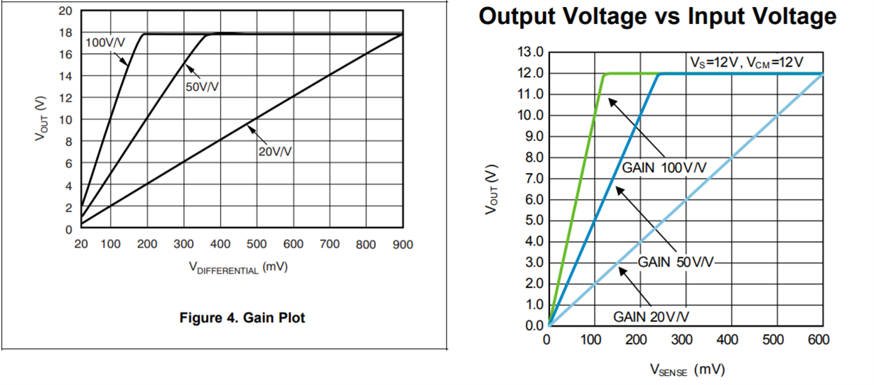
    However, if you still prefer to use the INA169 for high-side measurements, one benefit of the INA169 is that its gain can be adjusted with the load resistor.  The current to voltage gain equals the (Shunt Resistor)x(Load Resistor)/(1Kohm).  As for the INA200, this does have issues with low Vsense voltages.  The INA200's output behavior (Figure 1- left) can be contrasted with the LMP8640 (Figure 1 -right), which fixes the low sense voltage issue.  However, with the LMP8640, the sense pins must see voltages higher than -6V as opposed to the -18V on the INA200.

  • Hello Mihai,

    I have not heard back from you in a while. Were you able to decide on a current monitor? Do you have any further questions?
  • Hello Patrick, the INA240-Q1 that you recommended looks very good as I will have low sense voltages, thanks for pointing that out !
    I will use a 1 mOhm (or even 0.5 mOhm) sense resistor so the voltage will be very low.
    The main function will be actually for overcurrent protection (at 80-90A) so I would have liked to use a device with included comparator but it seems that such devices are not precise at low voltages (though I do not need a very high precision).
  • Hello Mihai,

    Glad we could point you to the INA240-Q1. As for a similar device with a comparator, you are correct, we currently do not have one. For high common mode devices that include a comparator, we only have the INA200, INA203, and INA206. All of which are not the most precise at low voltages.

    For now , I presume you have made your on decision on which device to proceed with. However, if you still have further questions, please feel free to open a new thread. Good luck on your DC motor system!
  • Hello Patrick, I have made the design using INA240, I will test it in the next days and get back to you - hopefully with good results !
    Thanks for your help !
    Mihai
  • Hello Patrick, I have tested the design with INA240 and it works fine until now, I have tested it at lower currents (up to 20A) and it looks quite accurate, we will test at higher currents next.

    There was however an issue with the INA240 getting damaged by (most likely) negative spikes, as I mentioned the circuit monitored by INA240 is activated with relays (H bridge) and it powers a DC brushed motor.

    I forgot initially to add the protection diodes at the relays and I assume there were negative spikes below -4V and they damaged the INA240.

    I have added the diodes and also a capacitor over the motor and afterwards there were no problems.  I have also two SMBJ75A  TVS over the inputs of the INA240.

    These should protect it from overvoltage however I am still concerned about negative spikes. Beside the diodes over the relays, the capacitor at the motor and the TVS are there other improvements in protecting the INA240 ?  In my tests I had no further problems but it will be used on the real equipment where other spikes can be present and longer wires and I would like to make sure it is protected as much as possible.

    One more note - I have used it initially on the high side (when it was damaged), after making the changes with the diodes and capacitor I have moved it to the low side (where it worked fine so far).

    Thanks,

    Mihai

  • Hello Mihai,

    Sounds like you are making good progress on your design. As for other suggestions, I do not currently have any as according to one of our TI designs, TVS diodes provide the most robust protection against transients. If you are interested in reading the document related to that TI design, it can be found here: http://www.ti.com/lit/ug/tidu473/tidu473.pdf.  In that document the performances of various transient protection methods are compared.


  • Hello Patrick, thanks for the link, however this document shows (more or less) a similar solution to the one that I used (with TVS).

    The issue is that the INA240 was damaged even with the TVS installed therefore I was suspecting a negative spike that  caused this failure.

    Do you have any suggestion about improving the situation with negative spikes ?

    Thanks,

    Mihai

  • Hello Mihai,

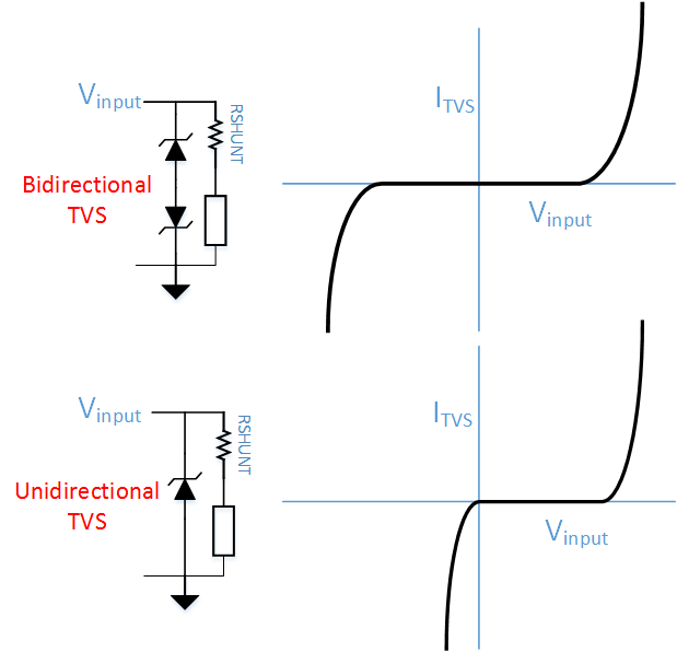
    My knowledge of TVS diodes is they have behavior similar to the diagram below.  Consequently I believe a unidirectional configuration would be best as you want to clamp the VCM at voltage above -6V and preferrably above -4V.   However, you still could use two separate TVS diodes that have different clamp voltages, as long as the negative clamp falls within the recommended operating range of the INA240.

    Aside from these TVS diodes, I do not have any further suggestions on how to protect your circuit. 

  • Hi Patrick, you are right, the unidirectional TVS should protect in both situations.

    But in this case I don't understand what caused the failure of the INA240 as I have used unidirectional TVS on both input lines (SMBJ75A as recommended in a reference design for INA240).

    As I mentioned the failure occurred when I tested without the diodes installed over the relays and motor so there were for sure high voltage spikes.

    After I replaced the INA240 and added the diodes at the relays and at the motor and also a capacitor at the motor it worked fine.

    Best regards,

    Mihai

  • Hey Mihai,

    With the details provided, I also cannot definitively tell you what in your system caused the failure. However, if you absolutely must know, I would suggest taking oscilloscope shots. Even with the TVS diodes, you may be able see if the VCM is clamped for a prolonged period of time at the negative of positive bound and thereby deduce which transient destroyed your part previously.
  • Hello Mihai,

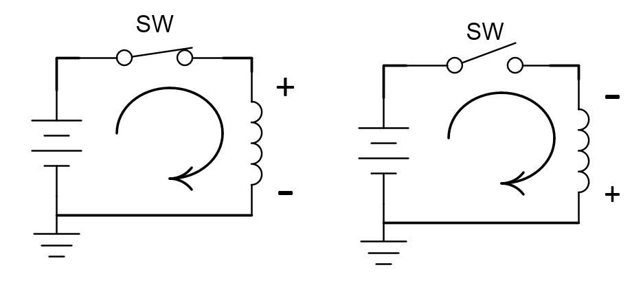
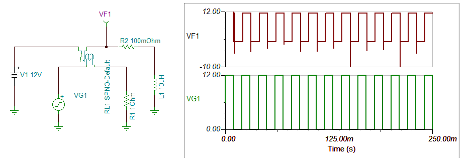
    I believe I have a possible explanation for why you saw the negative transients.  A motor can be seen as a set of inductors, which produce a magnetic field around them as current passes through them.  Voltage induced in a coil is directly related to the change in magnetic flux.  As the power supply is cutoff from the inductor, the voltage polarity of the inductor changes to maintain the flow direction of current through the coil. At this point the magnetic field rapidly collapses in the inductor.  Since the magnetic flux decay is so rapid, the corresponding voltage from the coil can be very large.  Below I have two figures to illustrate the point.  The first highlights the polarity change in the inductor, while the second is a simulation of inductor with power supplied and then cutoff.  If you want to read more on the topic, I would recommend looking up inductive kickback.

     Figure 1: Inductor Polarity Change

    Figure 2: Square wave in inductor causing Inductive kickback