This thread has been locked.

If you have a related question, please click the "Ask a related question" button in the top right corner. The newly created question will be automatically linked to this question.

INA193: Current Sensor used in a battery charging Application Fails after 10 charge cycles

Part Number: INA193
Other Parts Discussed in Thread: TMS320F28069, , INA200, INA203, INA271, INA270, INA240, INA282, INA139, AMC1301

Hi

  We are using INA 193 current sensor for a battery charging application. We are using it for 24V as well as a 48 V application.

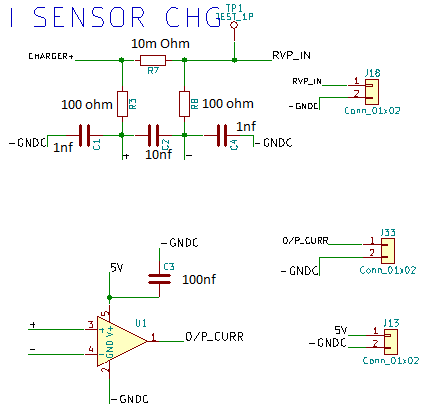
I have also attached the circuit used. It works well. After some 10 ~ 15 charge cycles, the current sensor failed.. ( Current sensor output is continouslly 0 volts).

The current measuring range is 0 - 5 A DC. We are using a 5 V power  supply whose ground is isolated from the battery negative ( whose current is being sensed).

  After the first failure, we replaced the sensor, again after some 10 ~ 15 charge cycles , once gain the sensor failed. 

The current sense resistor is connected  between charger +ve terminal and the battery +ve terminal. The output of the

INA 193 ic connected to an ADC of TMS320f28069..

Is it allowed to use this for a 24 V battery without any transient protection @ the sensor inputs ?

Is it allowed to use this for a 48 V battery without any transient protection @ the sensor inputs ?

What could be the other cause for the sensor output to go 0 volts... when it is sensing a current of around 3 A DC.. ?

Thanks

Lenin.

  • Hello Lenin,

    I am sorry you are experiencing this issue. Thanks for attaching schematic information. I do not see anything overtly wrong about this circuit, but some more debug information would be very helpful. Whether you need transient protection depends on how fast and large the signals are. Could you measure the TP1 voltage when the charger cycles are starting/stopping?

    Are the devices getting hot when they are breaking? Could you measure IB+ and IB- (voltages across R3 and R8) as well as IQ for a good part and bad part? I am also curious as to know if there is any voltage difference between INA193 ground and the battery/charger ground. Could you please measure this, if possible, with a multimeter?

    Thank you for your understanding.

    Best,
    Peter Iliya
    Current Sensing Applications

  • Hi Lenin,

    is any cabling involved to and from the INA193? Cables with their inductances can cause ringing and by this eventually destroy chip inputs and outputs. Also, ESD can easily enter your circuit via the cabling. So, whenever cabling is involved it's good design practise to mount TVS!

    Kai
  • Hi Peter

    Thanks for the response. Actually the failure happened, when we are tuning the PID controller, during which the current ( being sensed) was oscillating more than the normal condition ( around 0.4 A pk-pk @ an oscillating frequency of 50 kHz)..

    We are replacing an another sensor after which we could make all the measurements that you have mentioned. As of now with the faulty sensor we measured
    1. Battery Negative to Power Supply (used for INA 193) ground - It was around 22 V DC
    2. Voltage across R3 was around 0.01 V

    Could you pls clarify the below..

    1. So is there is any limitation on the di/dt of the current that being sensed ?
    2. The recommended common mode voltage and the supply voltage was mentioned as 12 V in the data sheet, however in our case , our Vcm goes upto 30 V/55 V DC ( 24 V /48 V battery charging application). Is that ok ? Also the power supply we are using is 5V DC.

    Thanks
    Lenin.
  • Hi Kai

    We are not using any cables. It's actually mounted in a PCB.

    Thanks
    Lenin.
  • Hi Lenin,

    nevertheless, I would strongly recommend to mount TVS.

    Kai
  • Hi Kai

    Is it required to mount the TVS @ both the differential inputs.. Can u suggest an TVS for this..

    Thanks
    Lenin.
  • Hey Lenin,

    1. What limits sensing a certain di/dt is mostly the slew rate of INA193.
    2. The part can accept a common mode voltage (votlage at Vin+, Vin- with respect to INA193 GND pin) of 80V. So this is fine, but keep in mind that if the difference between "Battery Negative" and INA193 GND (or 5V power supply ground) is 22V, then your common mode becomes 52V or 77V (depending on battery voltage), but this should also be fine.

    With voltage across R3 at 10mV, the IB+ is 10mV/100 Ohm = 100uA. This is out of spec because we specify IB+ to be +/-16uA maximum up to Vsense = 100mV. It is possible that you are creating some large ground loop that is increasing IB. Although I am unsure about how makes output go low.

    Once you place a new INA193 in your system, please immediately measure the VR3 and VR8, as well as, the difference in between the two ground potentials to see if these values change over time.

    Some questions:
    1. Why are you isolating the two grounds?

    2. Why is your shunt resistor R7 0.01Ohms? At 1A, Vsense = 1*0.01 = 10mV and thus Vout should equal 200mV, but this device will have trouble sensing voltage < 20mV. This is discussed in Section 8.4.2.3 of datasheet. Additionally, the input offset Vos can reach 2mV, which would account for 20% error if your Vsense is 10mV. While I don't think this has anything to do with your current issue, you may want to consider increasing the shunt resistor or considering other 80V parts like INA240, INA200, INA282, INA203, INA271, INA270.

    3. Is the INA193 driving any type of load?


    Best,
    Peter Iliya
    Current Sensing Applications
  • Hi Lenin,

    I cannot recommend a scheme using TVS, because I don't know your circuit. I can only say, that the INA139 cannot be easily destroyed. And if it gets destroyed something really bad must have happened. This can be inductive kick backs if cabling is involved or it can be the consequence of the use of isolated supplies which leaves the involved grounds separated and isolated from each other: Between isolated circuits no charge equalization can take place and there's a risk of the built up of electrostatic charge, which can discharge in an ESD event. ESD is an ultra-fast event and the discharge current path cannot be fully predicted. Even stray capacitance plays an important role. Eventually the ESD current runs directly through the INA139. As consequence you can end up with a destroyed INA139, without knowing the reason for it.

    Kai
  • Hi Peter

      Thanks for the response

    Once you place a new INA193 in your system, please immediately measure the VR3 and VR8, as well as, the difference in between the two ground potentials to see if these values change over time.

      - After placing the new sensor we found that the value is 1 mv. Also the voltage between the power supply Gnd and battery -ve have become zero.

    1. Why are you isolating the two grounds?

       - In the data sheet it has mentioned that the max voltage @ the differential inputs is 18 Volts. If the battery is not isolated from the ground, then the voltage @ the differential input will be equal to the battery voltage and hence will exceed the max limit of 18 V. Pls  correct me if i got it wrong. In our case the sensor is @ the high side..

    2. Why is your shunt resistor R7 0.01Ohms? At 1A, Vsense = 1*0.01 = 10mV

       Thanks for this input , we will change the sense resistor.

    3. Is the INA193 driving any type of load?

        It's just used to sense the battery charging current.

    Thanks

    Lenin.

  • Hi Peter

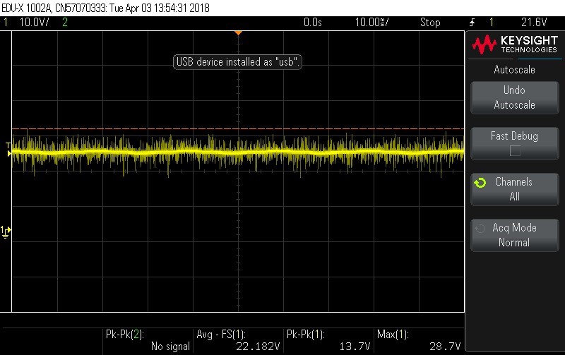
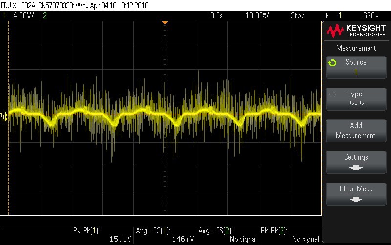
     As I mentioned in the earlier post the voltage between Power supply ground and battery -ve has come down to zero after changing the new sensor. I have also attached the two waveforms.

    Under Faulty Conditon

    Under Normal condition

    Thanks

    Lenin.

  • Hi Lenin,

    can you post a schematic of the whole setup?

    Kai
  • Hey Lenin,

    Thank you very much for data and scope shots. First off, you definitely want to connect the -ve (battery negative electrode) and Power supply/system grounds. The -18V to 18V range for analog inputs in Section 7.1 is a redundant error and this row should not be there. We apologize for this confusion. The common-mode rating of -16V to +80V is the actual VCM rating for the inputs, thus you can/should absolutely connect these grounds. Do this and then repeat the VR3/VR8 and ground measurements/waveforms.

    Sincerely,
    Peter Iliya
    Current Sensing Applications
  • Hi Peter

       I'm not sure about removing the isolation. Actually once we accidentally shorted this isolation. ( we were measuring the 

    battery voltage and the sensor o/p in the same scope ... the two channels were not isolated). After this the sensor failed 

    (sensor o/p becomes continuously zero V ).

     Apart from this we use an AMC1301 sensor for sensing the battery voltage. The same power supply is being used

    for both INA 193 and AMC 1301.. Shorting the power supply ground and the battery -ve will bypass the isolation of this AMC 1301..

    Hence I'm not sure if i could bypass this isolation....

    Also I felt that isolation would avoid the noise entering the micro controller, that's why we were using that AMC 1301 with isolation....

    Kindly suggest..

    Thanks

    Lenin.

  • Hey Lenin,

    Was this accidental connection of the grounds due to the oscilloscope probe being referenced to Earth ground? Were you able to gather valid, simultaneous measurements from INA193 and AMC1301 before the INA193 broke?

    What noise are you referring to? Is this common-mode noise at inputs of AMC1301? If the noise is common-mode noise at AMC1301 inputs, then this should be rejected by device, but if noise is differential across the shunt resistor, then this will not be blocked by isolation. The isolation is primarily meant to block voltages from input to output.

    Could please provide a full schematic? The AM1301 can only have a common-mode voltage of VDD1+0.5V with respect to GND1. If your GND1 is connected to -ve and you are sensing high-side, then the common-mode is around 40V and this would break the device.

    Regardless of the AMC1301 circuit, the INA193 should not have a isolated ground from the ground of battery.

    Sincerely,
    Peter Iliya
  • Hi Peter

    Was this accidental connection of the grounds due to the oscilloscope probe being referenced to Earth ground? Were you able to gather valid, simultaneous measurements from INA193 and AMC1301 before the INA193 broke?

        The AMC 1301 is being used for sensing the voltage of the battery which reads from a potential divider connected across the battery. Both these 

    sensors were connected to MCU ADC and based on these two signals the charge control was done, which happened perfectly for multiple charge cycles

    until the INA 193 failure happened

    What noise are you referring to? Is this common-mode noise at inputs of AMC1301? If the noise is common-mode noise at AMC1301 inputs, then this should be rejected by device, but if noise is differential across the shunt resistor, then this will not be blocked by isolation. The isolation is primarily meant to block voltages from input to output. 

    .  We assume the noise is a common mode..

    Could please provide a full schematic? The AM1301 can only have a common-mode voltage of VDD1+0.5V with respect to GND1. If your GND1 is connected to -ve and you are sensing high-side, then the common-mode is around 40V and this would break the device.

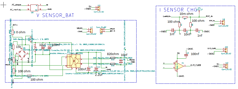
      I'm sharing the schematic associated with both the sensors below. The common mode voltage here would be less than 3 V. Pls refer schematic. We had no issues with AMC1301 till now.

    Regardless of the AMC1301 circuit, the INA193 should not have a isolated ground from the ground of battery.

      In that case do you mean to say that both cannot be used together ?


    Thanks

    Lenin.


  •  Hi Kai

     Pls find the schematic associated with all the sensing circuits.

    Thanks

    Lenin.

  • Hello Lenin,

    I am still unsure about what the load for the INA193 is or in other words what RVP_IN node (IN- pin of INA193) is actually connected to. You can certainly use the AMC1301 and INA193 in the same system, but I am not sure how practical this really is. The AMC1301 can isolate its drive output circuitry from noise and large spikes on a high-voltage common-mode line so it is perfectly normal to separate the GND1 and GND2 of this device.

    For the INA193 it is not normal operation to separate the grounds of the bus voltage and the ground pin of the INA193. You will experience complications from ground loops and increasing voltage potentials between the grounds, which will vary the absolute votlage at the input pins.

    If you connect the ground pin of the INA193 (currently -GNDC) to the ground of the system (I'm guessing -ve or GND1, I'm not sure with schematic not showing where IN- pin is connected), then the INA193 will operate in its specified configuration. Additionally, the output signal from the AM1301 should not be affected since it will isolate its output and input regardless.

    Sincerely,
    Peter Iliya
    Current Sensing Applications
  • Hi Lenin,

    I aggree with Peter.

    I additionally think, that over the -GNDC terminal dangerous potentials could impact your circuit. Surges and other overvoltages from mains voltage can enter your circuit and can cause dangerous equalization current spikes.

    It's difficult to tell anything useful, without knowing the whole circuit, but I would connect -GNDC to protective earth via a 1M resistor in parallel with a 10n cap. This soft grounding technique could shunt overvoltage spikes to protective earth and would eliminate the develop of dangerous charge.

    All other signal ground potentials should also have such a path to protective earth (soft grounding).

    Kai
  • Hello Lenin,

    You are powering the VDD1 and GND1 pins of your AMC1301 with a floating Zener voltage drop, so connecting the negative battery terminal with your INA193 ground will not affect the performance of the AMC1301. Regardless, the AMC1301 can have the GND1 and GND2 pins be connected to same ground plane and function according to the specified electrical characteristics. I am not sure what your battery negative is actually connected to, but ground nodes/planes are low-impedance and thus should not be noisy. I believe if you connect everything to one ground, any noise you are seeing from the battery charging circuit will not couple to the output of your INA193 or AMC1301.

    I ask you to try this because running the INA193 with its GND pin isolated from its input common-mode voltage is a configuration we cannot guarantee since we do not specify the part in this configuration.

    Sincerely,
    Peter Iliya
    Current Sensing Applications
  • Hi Peter

     Thanks for the response. We could try it out as per your suggestion. However  would appreciate

     if the data sheet of the INA 193 is updated, which specifies a maximum  of 18 V @ the differential inputs.

    Thanks

    Lenin.