This thread has been locked.

If you have a related question, please click the "Ask a related question" button in the top right corner. The newly created question will be automatically linked to this question.

INA193: CURRENT SENSOR FAILED REPEATEDLY IN BATTERY CHARGER

Part Number: INA193

Hii

We are currently using INA193AIDBVT current sensor for a battery charging application. We are using this sensor for both 24V and 48V chargers. At starting few cycles (10 to 15) its works fine, after that sensor accuracy gets slightly down then after few cycles( 1 to 2) it failed.now sensor output is zero. we are measuring the current from 0 to 5A.

current sensor is placed between Charger Positive and Battery Positive. Sensor ground and battery negative are not connected. battery negative is isolated from microcontroller (tms320f28069m) ground and sensor ground. sensor and micro controller grounds are same.

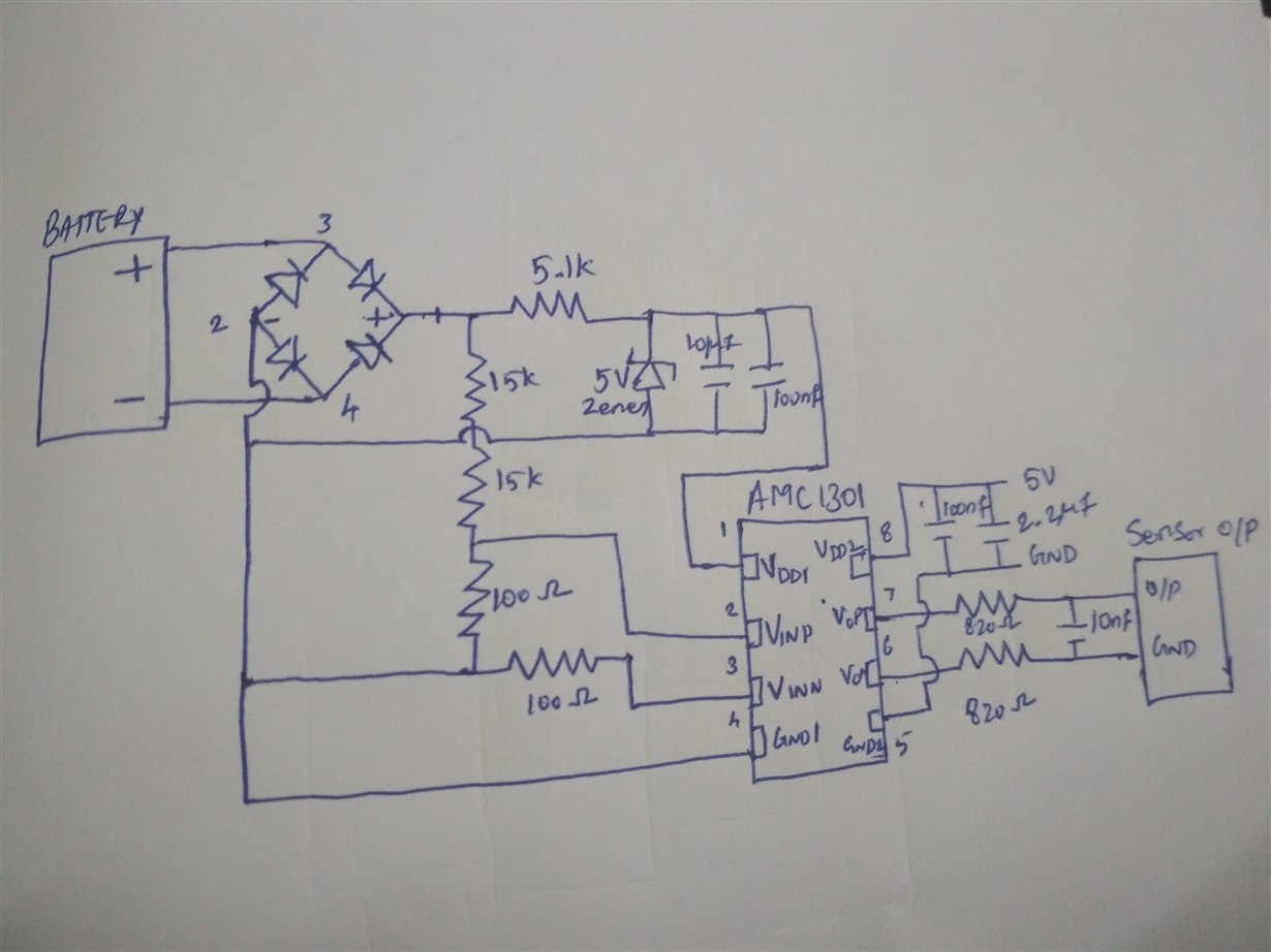
Also we are using AMC1301 for voltage sensing. which requires two isolated power supplies. one we get from the separate 5V power supply (its negative is connected to micro controller ground and sensor ground) another one we get from the battery voltage.for this reason we are not connecting the battery negative with INA193 ground. 

current sensor is repeatedly failed. what could be the possible reason for this failure? 

is it mandatory to connect battery negative with sensor ground?

if i connect battery negative with sensor ground, will AMC sensor fail?

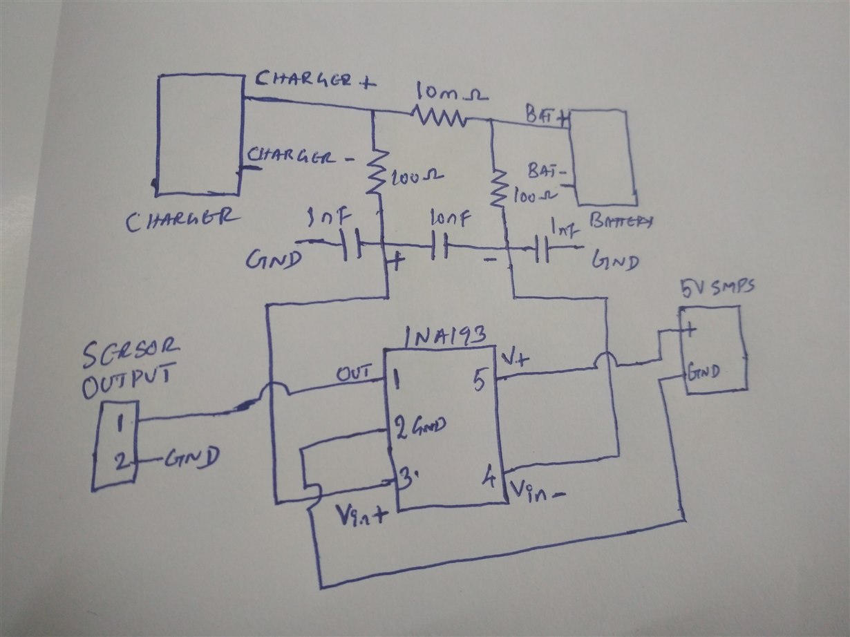
Here i attached the sensor schematic diagram for your reference.

thank you

with regards

KALYAN


  • Hello Kaylan,

    Thanks for considering to use TI in your design. I suspect you are operating the device such that you are exceeding an absolute max condition. Your ground to the INA193 device should be connected such that the common mode does not go beyond -16V and such that the differential between the INA193 supply and INA193 ground does not exceed 18V. Would it be possible for you to replace the broken device and get oscilloscope shots of these voltages? Also can you provide a simple diagram of the ina193 device connections, including the ground, supply, and output?
  • Hi Kalyan,

    unfortunately, your schematic is totally unreadable...

    Kai
  • Hi Patrick

    Thanksfor the response

    Your ground to the INA193 device should be connected such that the common mode does not go beyond -16V

        The sensor is connected to a battery ( Max Voltage 55) , hence at the upper side it is limited to 55 and I don't see 

    any possibility for it to go less than 0V.

     differential between the INA193 supply and INA193 ground does not exceed 18V

      I assume you are talking about the supply voltage, in this case it is 5 V.

    herewith i attached the individual circuit diagrams of both INA193&AMC1301..

    THANKS

  • Hi Kalyan,

    in my eyes this circuit is total overkill. :-) I don't see any need for this total isolation. I don't see any need to use the AMC1301 and the bridge rectifier either. I would reference each GND of the circuit directly to the -battery terminal. Create a star ground point there. Connect the GND of INA193 to this point. Have the 10mR shunt connected directly at the +battery terminal. Keep all involved cables between shunt, INA193 and battery as minimal as possible. That's how the INA193 is expected to work!

    If you want to monitor the battery voltage, use a simple voltage divider which you directly connect from the +battery terminal to the -battery terminal.

    If you still need an isolation between the -battery terminal and the GND of your data aquisition system you can use isolators for the analog signals. But at least you have now a stable GND for the current measurement and the voltage measurement.

    Kai
  • Hello Kalyan,

    Thank you for clarifying the setup. I understand you do not see the possibility, but can you at least verify it. Your INA193 ground being isolated from the battery and charger ground, I believe is creating voltage conditions that deviate from your expectations and I suspect these conditions are breaking the part. If you can provide oscilloscope shots of the differential between the INA193 Vin+ and the INA193 GND pins, we can completely rule this cause out and start considering other causes.
  • Hello Kaylan,

    Have you made any progress on debugging your circuit?
  • sir,

    We tested the circuit by connecting the INA193 ground  with battery negative, once again the sensor failed.

    What could be the maximum allowed voltage  between vin+ to battery negative and Vin- to battery negative?

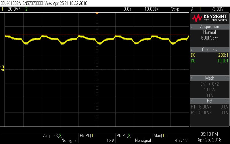
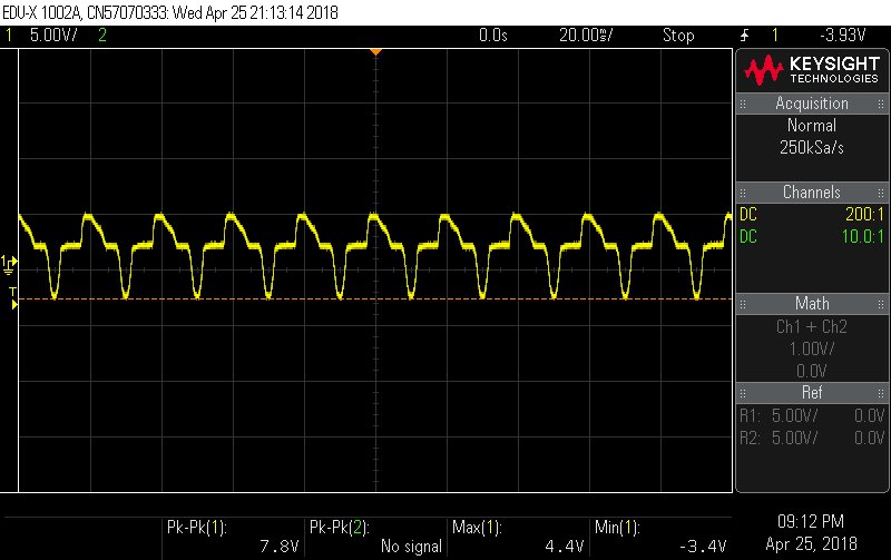
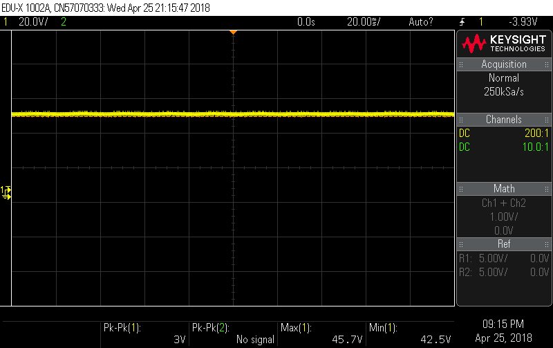
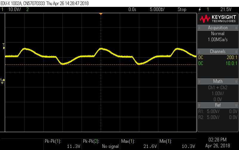
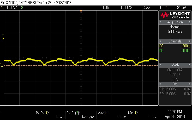
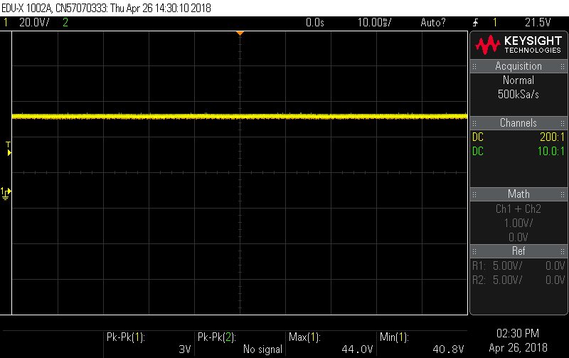
    herewith i attached the voltage waveforms between Vin+ and battery negative for different conditions

    1. battery and VCC both ON

    2.without battery and with VCC

    3.with battery without VCC

    1.

    2.

    3.

    thanks

    with regards

    kalyan

  • Hello Kalyan,

    Can you clarify what you meant by 10 to 15 cycles? Is this 15 cycles of plugging and unplugging the charger or cycles of the AC current pulsing into the charger? Also can you provide scope shots for the transition between the various states? Such as when only the battery is connected to when the charger is connected or when the charger is disconnected? Or could you show the transition of when the battery is connected to when the INA193 device actually powers on? It is possible that the abrupt change in the common-mode is slowly breaking the device.
  • Hi Kalyan,

    I think it's time now to add some TVS from the inputs to GND.

    Kai
  • Hi Patrick

    10 to 15 cycles refers to the battery charging cycle. One charging cycle lasts for about 8 hour. I have also attached some waveforms of the Vin+ wrt ground after replacing a new INA193 sensor, which is currently working. We have removed the direct connection between INA193 ground and Battery -ve. Now INA193 ground is connected to the battery -ve through a 1 Mohm resistor ( with 10 n cap connected in paralell).

     The waveform shows the minimum voltage of Vin+ wrt ground  is not going below zero volt, which validates our previous assumptions.

    However we are not sure if its going to fail after some time.

    The only repetitive observation before each failure was, 

    Whenever there is abnormal variations in current say huge ripples or high inrush etc (since we are in the testing mode ), the sensor failed..

    Thanks

    Kalyan.

    Fig 1 - Vin + wrt INA193 Gnd (With Battery and Vcc ON)

    Fig 2 (above) - Vin + wrt INA193 Gnd (With outBattery and Vcc ON)

    Fig 3 (below) - Vin + wrt INA193 Gnd (With Battery and Vcc OFF)

    kjsd

  • Hello Kalyan,

    Thank you for posting your oscilloscope shots again. As you noted, the part breaks when the current exhibits huge ripples or high inrush. These were one of the conditions I was actually hoping you would capture on your oscilloscope when I was asking for you to capture the transitions between various power states. I presume these huge ripples and inrushes only occur at the beginning of the charging process. So to quickly acquire these, I would turn on and turn off (or connect and disconnect) your charger to a depleted battery. Capture the common mode voltage transient during turn on/ connection and the transient during turn off/disconnect (not the common mode several seconds after turn on). I suspect due to parasitics in the circuit and board layout, you will see conditions that violate our device's specifications. If this is indeed happening, a tvs diode between the input and device ground will save your device. Alternatively you could have a ferrite beads in series with your input filter resistors.
  • Hello Kalyan,

    Have you made any progress with the debug? Or did you try putting any transient protection on your INA193?
  • Hello Kalyan,

    As I have not heard from you in a while, I presume you have resolved your issue and/or are proceeding with transient protection on your input pins. As such, I will close this thread. However, if you still have further questions about this matter, feel free to respond in this thread below. Otherwise if you have questions on a different device, feel free to open a new thread.