This thread has been locked.

If you have a related question, please click the "Ask a related question" button in the top right corner. The newly created question will be automatically linked to this question.

INA219: Measuring current during GSM Transmission

Part Number: INA219

I am using the INA219 chip which is connected to an 8-bit 8mhz mcu via i2c.

I am using it to measure the current consumption during a GSM transmission

on a SIM800c modem connected to the same mcu via serial ports. But because my mcu is busy

during the transmission I am not able to record the instantaneous current and the

cumulative power consumed during the transmission. Also, because GSM modems

have high peak transmission bursts I am not even able to detect these bursts.

Can you please suggest a way around these problems?

Will I need another deticatgedMCU connected with the INA219 just to log the current

consumption while the main MCU communicates with the GSM module?

  • Hey Karan,

    Thank you for using the TI forum.

    If your MCU is too busy to read the current value during the transmission, then you will either need two MCU's as you mentioned, or you will need to find one MCU that can handle both at the same time.

    Why are you unable to read the high peak transmission bursts? Is it because the peak voltage is too high or because they happen too fast? Could you send me an oscilloscope capture of the transmission bursts? Also, it would be useful if you could send a schematic of your current measurement implementation as well.
  • Hey
    Thanks for your reply.

    If I have to use a microcontroller, I could just use the adc in the microcontroller
    and avoid using the ina219 completely right? What will the benefit of the ina219
    chip then?

    Also, PFA the sample output from the SIM800H datasheet. Don't have an access
    to an oscilloscope right now but I had checked it earlier and its exactly the same
    as attached.

    For the schematic and code I am using the breakout boards by adafruit so you can find
    everything here:
    INA219: cdn-learn.adafruit.com/.../adafruit-ina219-current-sensor-breakout.pdf
    SIM800H:cdn-learn.adafruit.com/.../adafruit-fona-mini-gsm-gprs-cellular-phone-module.pdf

    INA219 is powered at 3.3V via the microcontrollers GPIO pin. The SDA SCL lines are pulled up
    via 5k resistors to 3.3V Vcc. The sim800H is powered by a 6V lithium ion battery pack connected
    at Vin- and the cellular module at Vin+.

    If you still need a schematic let me know, Il have to make one, but the connections are very basic.

    Rgds
    Karan
  • Also, I am facing another issue suddenly. 2 out of 3 of my chips have randomly started reporting wrong Bus and Shunt voltages. 1.21 V for 3V changing randomly almost like garbage values. What could be the reason. I've tried everything - changing microcontroller, pullups etc. One chip works and the other 2 don't while all 3 have been stored and used similarly.
  • Hello Karan,

    I'm not sure what the capabilities/resolution of the ADC in your MCU are, but the INA219 allows you to do a High-Side current measurement.  If your MCU ADC is referenced to GND, then it would force you to do a Low-Side measurement, which will throw off your system ground. Also, the INA219 has a programmable gain, giving you more options for the input voltage sense range, as shown in the picture below. 

    So, if your MCU ADC can do a high side measurement with the input voltage range and the resolution you need, then you will not need the INA219, but if it can not, then you would need the INA219.

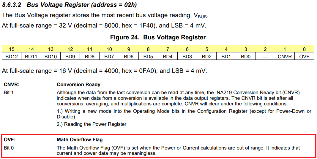
    For your other concern, if you are getting wrong values from the INA219 you may want to look at the overflow flag. As noted below, if you have any overflow in the calculations, then the data may be meaningless.

    For the issue of the high peak transmissions, if the current is too high to measure, then you may need to look at changing your input voltage sense range.