• Join
  • Sign In with my.TI Login
Texas Instruments
  • Products
  • Applications
  • Tools & Software
  • Support & Community
  • Sample & Buy
  • About TI
Sample & Purchase Cart Sample & Purchase Cart
  • Search
  • Advanced
TI E2E™ Community
  • Support Forums
  • Blogs
  • Groups
  • Videos
  • 简体中文
  • More ...
TI Home » TI E2E Community » Support Forums » Amplifiers » /etc... Amplifiers & Other Linear » /etc... Amplifiers & Other Linear Forum » LOG114 Input Resistance
Share
/etc... Amplifiers & Other Linear
  • Forum
  • Announcements
  • E2E Wiki
Options
  • Subscribe via RSS

LOG114 Input Resistance

LOG114 Input Resistance

This question is not answered
paul solomon
Posted by paul solomon
on Dec 20 2012 10:30 AM
Prodigy70 points

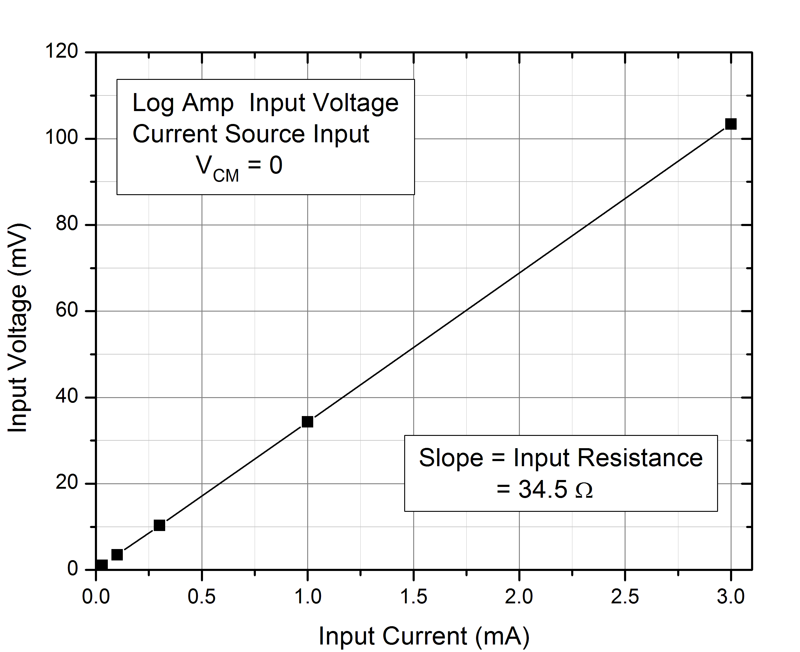
I am using the LOG114 amp to monitor an exponentially varying pressure sensitive resistor and using the internal circuitry to generate a bias of -0.1V. When the resistance value is very small (approx. 50 ohms) i notice that the bias voltage drops, as if there is a resistor of about 35 ohms is series with the input. This resistor does not feature in the data sheets and I wonder if it is included in the IC package for input protection. Since it limits the range of resistances I can measure I wonder it there are versions of the LOG114 that do not  include it or use a lower value?

Thanks, Paul

Report Abuse
  • Reply
You have posted to a forum that requires a moderator to approve posts before they are publicly available.
All Replies
  • Thomas Kuehl
    Posted by Thomas Kuehl
    on Dec 20 2012 12:33 PM
    Mastermind24240 points

    Hi Paul,

    I have some questions and comments:

    • Is the internal circuitry that generates the -0.1 V bias derived from the LOG114, or some other part of the circuit?
    • The log amplifier input does not have any added series resistance at the input.
    • Beyond 1 mA of input current the log conformity of the LOG114 becomes less linear. This is evident from the bottom 4 graphs on page 7, in the data-sheet. I wonder if that might be a factor producing the equivalent of the series input resistance effect you are seeing?
    • Are you able to provide your schematic?

    Regards, Thomas

    PA - Linear Applications Engineering


    Report Abuse
    • Reply
    You have posted to a forum that requires a moderator to approve posts before they are publicly available.
  • paul solomon
    Posted by paul solomon
    on Dec 20 2012 13:34 PM
    Prodigy70 points

    Thomas,

    Thanks. Here is my schematic:7824.piezo_logamp.pdf. The bias voltage is generated using A5 and applied to the Vcm_in terminal. When A2 is in its operating regime there should be no voltage between Vcm_in  and i2 (virtual ground) yet I get ~25mV when a 100 ohm resistor is connected between the input and ground on the 100mv setting (i.e. there is 75mV across the resistor. The Output voltage is still within spec. The effect is linear. When I choose the 10mv setting I get 7.5mv out. Now the current is 10x less so it is not a saturation effect, but a linear input resistance (Req = 25mv/750uA = 33 ohm).

    Paul

    Report Abuse
    • Reply
    You have posted to a forum that requires a moderator to approve posts before they are publicly available.
  • Thomas Kuehl
    Posted by Thomas Kuehl
    on Dec 20 2012 17:14 PM
    Mastermind24240 points

    Hi Paul,

    I am thinking about the result you are observing. Disecting your latest response:

     The bias voltage is generated using A5 and applied to the Vcm_in terminal. - Okay, you are depending on the virtual ground I2 input to track the adjustable VCM level and develop the current through RDUT . That seems like a good method.

     When A2 is in its operating regime there should be no voltage between Vcm_in  and i2 (virtual ground) - Other than the offset voltage that is what I would expect too.

    yet I get ~25mV when a 100 ohm resistor is connected between the input and ground on the 100mv setting (i.e. there is 75mV across the resistor.The Output voltage is still within spec  - As you described earlier it is if there is a resistor in series leading from RDUT to the I2 input. Since this is a linear effect are you seeing that the output voltage is within the correct range at all current settings?

    The effect is linear. When I choose the 10mv setting I get 7.5mv out. Now the current is 10x less so it is not a saturation effect, but a linear input resistance (Req = 25mv/750uA = 33 ohm).  - So in the case of the 10 mV setting you would 7.5 mV across the 100 Ohm resistor and 2.5 mV across the log amp inputs. The I2 input current would be 75 uA and the proposed series input resistor would remain at 33 Ohms. Is that correct?

    How are you making the actual measurement? Are you connecting a DVM between VCM and the I2 input and making a direct measurement, or is the voltage being extrapolated based on the level observed at Vo4? The LOG114 is a wide-band log amplifier fabricated on a high-speed process and one has to be careful when making measurements not to cause high-frequency oscillation. DC errors can occur when oscillation is present.

    Regards, Thomas

    PA - Linear Applications Engineering

    Report Abuse
    • Reply
    You have posted to a forum that requires a moderator to approve posts before they are publicly available.
  • paul solomon
    Posted by paul solomon
    on Dec 20 2012 18:32 PM
    Prodigy70 points

    Thomas,

    Thanks for taking the time on this. I measured the voltages directly on the inputs with a DVM. I did not check on the scope while I was doing this measurement but I did check previously. The amplifier did pick up some 60Hz at high input resistors (>10Mohm) but not at the low values we are talking about. The amplifier was remarkably stable. I don't think AC oscillations are the problem, although I will check more thoroughly. The effects I am seeing are linear and predictable, fully consistent with a simple series resistor. This resistor would not affect the Vout vs Iin transfer function of the amp so maybe for this reason it is not seen on normal testing. I would appreciate it if you are able to find any info on this.

    Thanks,

    Paul

    Report Abuse
    • Reply
    You have posted to a forum that requires a moderator to approve posts before they are publicly available.
  • Thomas Kuehl
    Posted by Thomas Kuehl
    on Dec 21 2012 16:07 PM
    Mastermind24240 points

    Hi Paul,

    I have been going over the internal schematic for the LOG114 die looking for something that might explain the series input resistor phenomena. Basically, the amplifier input pins go directly to a JFET differential pair and the input ESD protection consists of normally-off current steering diodes to the supply rails. Therefore, I am not finding anything that simply acts as a series resistance. It appears to be something much less obvious then that.

    The LOG114 is most often driven by a current source such as a photodiode. The impedance asspciated with that kind of current source is very high. Your application is quite different in that it involves a series voltage source with a low resistance; nevertheless a source of current, but with much lower impedance than something like a photodiode. This operating condition is more similar to what is described in the data-sheet Voltage Inputs section, on page 18 - except in this case the resistances are very low.

    I have been discussing your inquiry with on of my colleagues and I will let you know if we hit upon anything that provides an explanation. Please note that the support level here in PA-Linear Applications will be much lower during the holidays and response times will lengthen.

    Happy Holidays!

    Thomas

    PA - Linear Applications Engineering

    Report Abuse
    • Reply
    You have posted to a forum that requires a moderator to approve posts before they are publicly available.
  • paul solomon
    Posted by paul solomon
    on Dec 21 2012 19:46 PM
    Prodigy70 points

    Thomas,

    Is the JFET pair part of the input amp of is this part of the ESD protection network?

    It should be easy to measure the input resistance, just input a current, e.g. 1mA, and measure the input voltage. You might need to isolate the DVM at the input with a resistor (e.g. 100k) to block noise from the DVM. It would be interesting to see if you get the same value for the input resistance that I do.

    Paul

    Report Abuse
    • Reply
    You have posted to a forum that requires a moderator to approve posts before they are publicly available.
  • paul solomon
    Posted by paul solomon
    on Dec 30 2012 19:43 PM
    Prodigy70 points

    Thomas Kuehl

    Hi Paul,

    I am thinking about the result you are observing. Disecting your latest response:

     The bias voltage is generated using A5 and applied to the Vcm_in terminal. - Okay, you are depending on the virtual ground I2 input to track the adjustable VCM level and develop the current through RDUT . That seems like a good method.

     When A2 is in its operating regime there should be no voltage between Vcm_in  and i2 (virtual ground) - Other than the offset voltage that is what I would expect too.

    yet I get ~25mV when a 100 ohm resistor is connected between the input and ground on the 100mv setting (i.e. there is 75mV across the resistor.The Output voltage is still within spec  - As you described earlier it is if there is a resistor in series leading from RDUT to the I2 input. Since this is a linear effect are you seeing that the output voltage is within the correct range at all current settings?

    The effect is linear. When I choose the 10mv setting I get 7.5mv out. Now the current is 10x less so it is not a saturation effect, but a linear input resistance (Req = 25mv/750uA = 33 ohm).  - So in the case of the 10 mV setting you would 7.5 mV across the 100 Ohm resistor and 2.5 mV across the log amp inputs. The I2 input current would be 75 uA and the proposed series input resistor would remain at 33 Ohms. Is that correct?

    How are you making the actual measurement? Are you connecting a DVM between VCM and the I2 input and making a direct measurement, or is the voltage being extrapolated based on the level observed at Vo4? The LOG114 is a wide-band log amplifier fabricated on a high-speed process and one has to be careful when making measurements not to cause high-frequency oscillation. DC errors can occur when oscillation is present.

    Regards, Thomas

    PA - Linear Applications Engineering

    Report Abuse
    • Reply
    You have posted to a forum that requires a moderator to approve posts before they are publicly available.
  • paul solomon
    Posted by paul solomon
    on Dec 30 2012 20:09 PM
    Prodigy70 points

    Thomas,

    Happy New Year!

    I did a calibration on my logamp by setting Vcm=0 and applying input currents from a Keithley current source. At the same time I measured the input voltage (using a 5K resistor for isolation) and monitored the output on the scape. As you see the logamp is very well behaved and there appears to be a resistor or 34.5 ohms in series with the input. It is curious, perhaps just a coincidence, that the departure from the log-linear relationship at high currents can also be attributed to a resistor of about 30 ohms in series with the diode.

    Paul

    Report Abuse
    • Reply
    You have posted to a forum that requires a moderator to approve posts before they are publicly available.
  • Thomas Kuehl
    Posted by Thomas Kuehl
    on Jan 03 2013 15:51 PM
    Mastermind24240 points

    Hello Paul,

    I am going to take the LOG114 into the lab and see what we find. I'll report back when I have something for you.

    Thomas

    PA - Linear Applications Engineering

    Report Abuse
    • Reply
    You have posted to a forum that requires a moderator to approve posts before they are publicly available.
  • paul solomon
    Posted by paul solomon
    on Jan 03 2013 16:08 PM
    Prodigy70 points

    Thomas,

    Great! Waiting for the results. An interesting aside: the effects of the log-diode series resistance and the input series resistance work in opposite directions so under some conditions (Vbias ~0.1v) they compensate each other.

    Paul

    Report Abuse
    • Reply
    You have posted to a forum that requires a moderator to approve posts before they are publicly available.
  • Thomas Kuehl
    Posted by Thomas Kuehl
    on Jan 03 2013 17:40 PM
    Mastermind24240 points

    Hi Paul,

    A couple of quick measurements using a LOG114 EVM and input currents of 1 mA (100 mV VCM and 100 Ohm input resistor) and 100 uA (100 mV VCM and 1 kOhm resistor) yielded an equivalent phantom input resistor of about 24 Ohms. This is different than the 34 Ohms you measured, but does support your finding that there is a series resistance.

    I am going to attempt to get the latest schematic and layout for the LOG114, but that will take some doing. The original schematic I reviewed was an early version and something could have been changed at a later time. Also, the die layout might reveal some unexpected resistance in the input circuit path. Metal resistance and via resistances between layers might account for tens-of-ohms of resistance.

    Regards, Thomas

    PA - Linear Applications Engineering

    Report Abuse
    • Reply
    You have posted to a forum that requires a moderator to approve posts before they are publicly available.
TI E2E™ Community
  • Support Forums
  • Blogs
  • Videos
  • Groups
  • Site Support & Feedback
  • Settings
TI E2E™ Community Groups
  • TI University Program
  • Make the Switch
  • Microcontroller Projects
  • Motor Drive & Control
Other Communities
  • Deyisupport
  • Designsomething.org
  • beagleboard.org
  • TI on Element 14
  • TI on TechXchangeSM
Other Technical & Support Resources
  • WEBENCH® Design Center
  • Product Information Centers
  • Technical Documents
  • TI Design Network
  • TI Technical Articles
  • TI Training

All content and materials on this site are provided "as is". TI and its respective suppliers and providers of content make no representations about the suitability of these materials for any purpose and disclaim all warranties and conditions with regard to these materials, including but not limited to all implied warranties and conditions of merchantability, fitness for a particular purpose, title and non-infringement of any third party intellectual property right. TI and its respective suppliers and providers of content make no representations about the suitability of these materials for any purpose and disclaim all warranties and conditions with respect to these materials. No license, either express or implied, by estoppel or otherwise, is granted by TI. Use of the information on this site may require a license from a third party, or a license from TI.

Content on this site may contain or be subject to specific guidelines or limitations on use. All postings and use of the content on this site are subject to the Terms of Use of the site; third parties using this content agree to abide by any limitations or guidelines and to comply with the Terms of Use of this site. TI, its suppliers and providers of content reserve the right to make corrections, deletions, modifications, enhancements, improvements and other changes to the content and materials, its products, programs and services at any time or to move or discontinue any content, products, programs, or services without notice.

Follow Us Texas Instruments on Facebook Texas Instruments on Twitter Texas Instruments on LinkedIn Texas Instruments on Google+
TI Worldwide | Contact Us | my.TI Login | Site Map | Corporate Citizenship | mobile m.ti.com (Mobile Version)

TI is a global semiconductor design and manufacturing company. Innovate with 100,000+ analog ICs and
embedded processors, along with software, tools and the industry’s largest sales/support staff.

© Copyright 1995-2013 Texas Instruments Incorporated. All rights reserved.
Trademarks | Privacy Policy | Terms of Use