This thread has been locked.

If you have a related question, please click the "Ask a related question" button in the top right corner. The newly created question will be automatically linked to this question.

xtr116 performance below 1mA

Other Parts Discussed in Thread: XTR116

I'm looking to implement a low-power 2-wire current loop where my signal current will range about 250uA to 450uA (not 4-20mA) using the XTR116. 

The data sheet seems to say the xtr116 can do this under these conditions:

xtr116 quiescent current + Iret < 250uA,

Iin*100 > xtr116 quiescent current + Iret

Is that right?  Comments?

Also, with Io < 450uA and V+ - V(Io) < 24V, is it necessary to use an external transistor Q1?   (power dissipation of the part will be less than 0.01W)  Comments?

My lab tests look good so far.  On thing I noticed was not having the external transistor Q1 seemed to improve accuracy by a couple of uA, at least towards the low end of my scale.  Comments?

This application is a departure from 4-20 mA but the linear range spec is listed as 250uA to 25mA and I can't find anything else in the spec's which indicates I can't do this.  Comments?

Thank you!

  • Hello Kris,

    This is an interesting application, could you provide some information about what type of sensor it interacts with as well as what type of control equipment the 250uA - 450uA output is connected to?  We can start a private conversation if you prefer.

    We'll look into your application and questions to determine if the XTR116 will perform as specified in the datasheet and will respond back later today.

  • Hello,

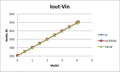
    We reviewed the product datasheet and agree that there doesn't appear to be any limiting factors for operating the device in this limited low output current range.  However, to be sure we setup the circuit in the lab and configured it for a 250uA - 450uA output from a 0V - 4.096V input.  This required an input resistance of 2048.7k and an offsetting resistor of 1638.5k connected to the 4.096V VREF output.

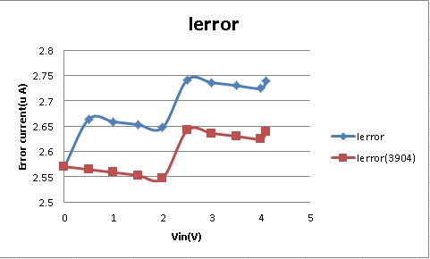
    The results look good and the errors seem in line with what's expected based on the datasheet specs.  See below:

    2311.XTR116_250uA-450uA.xlsx

    Here are some direct answers to your questions:

    1.) The XTR116 can be operated with or without the external transistor in all applications.  However, in standard 4-20mA output applications with higher loop-supply voltages, the power dissipated in the XTR results in significant internal temperature drift which results in drifting accuracy as the chip heats/cools with output current. With a lower loop-supply and such a small output current you'll likely notice very little change in performance between the two configurations.  However, even the small current flow will still result in some amount of power dissipation and therefore self-heating so the circuit performance may improve by moving that power out of the IC.

    2.) We actually observe the same thing and aren't exactly sure what to make of that.  The performance should be largely the same with/without the external transistor.  

    3.) See main body of post, looks like it will work fine.  I'd still like a little information on where/how this circuit will be used for my own understanding.

    Thanks!

  • Thank you for your response.

    Your results look similar to mine.  I see your red trace is with an external 3904 npn.  Is the blue trace with no external transistor? 

    In your data it looks like you got slightly better accuracy WITH the external transistor, though in both cases the error is within a couple of uA.  It seemed like I got slightly better accuracy without the external npn, though that was early on and before I tested more systematically, over temp.  I will have to re-run my with/without external npn test.

    Sure, we can discuss this by email.  I was away from the office today.  I can communicate in detail tomorrow.  What's your email?

  • Hello Kris,

    Yes, the blue trace uses the transistor internal to the XTR116.  

    Perhaps the discrepancy with/without the transistor is simply due to the polarity of the bias currents and/or offset voltage in the circuit and depending on the device one may be slightly lower/higher than the other.  Both are close and display the same trend.

    I'll message you with my e-mail.