This thread has been locked.

If you have a related question, please click the "Ask a related question" button in the top right corner. The newly created question will be automatically linked to this question.

floated 1Mhz sine wave generator

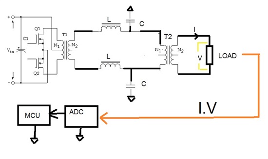
I have a problem to resolve.

I have a floated 1Mhz  sine wave generator that output

100VRMS  Max on 200 ohm load.

I need to measure the  output voltage and the output currant

On the 200 ohm  load.

Duos anyone have an idea what is the best way to do that?

  • Hello Aharon,

    This is a difficult task for semiconductors because of the high voltage, high current and frequency involved, and possibly the need to keep the output circuit floating. I expect that you will have to use a current sense transformer to avoid adding a voltage drop in the load circuit and maintain isolation from ground. Also, it is probably best to use a step-down isolation transformer to sense the voltage across the load and bring the voltage into the input range of semiconductor amplifiers. Both the current sense and step-down transformers could be ground referenced like your ADC. Both would need to be designed for use at 1 MHz.

    The transformer outputs can be translated to voltage levels useable with multiplexers and operational amplifiers. There are many multiplexers and high-speed operational amplifiers that would have sufficient bandwidth to process and amplify the signals so that they can be applied to the ADC.

    Regards, Thomas

    PA - Linear Applications Engineering