This thread has been locked.

If you have a related question, please click the "Ask a related question" button in the top right corner. The newly created question will be automatically linked to this question.

TI UA741 As Constant Voltage Source

Other Parts Discussed in Thread: UA741, TLV2470, TLE2426

Hello all,

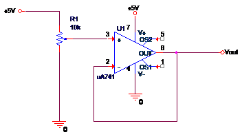
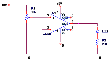
I'm designing a DC power supply and am currently prototyping with a UA741 op amp. I put together a variable voltage follower circuit, with the op amp, in hopes of creating constant voltage source. Without a load (Diagram 1) it operates as expected; the output voltage gets close to the top rail but not so close to the bottom rail. However when I set the non-inverting input to 5V and put a load on the output (Diagram 2) there is a large voltage drop between the non-inverting input and output; about 1.4V. This isn't the behavior I expected. I thought the idea of an op amp was that it will supply the necessary output current to keep the input voltage differential close to zero. Could it be that this op amp simply isn't good enough for this type of application? Where am I going wrong?


Diagram 1:

Diagram 2:

  • Hi Alex,

    The venerable UA741 is not specified as a single supply operational amplifier i.e. it is intended to use dual, +/- supplies. A single, +5 V supply barely powers the amplifier and results in a very limited common-mode input voltage range (VICR) and output swing capability (VOM). Even when the UA741 is operated with its nominal +/-15 V supplies, its VICR range is about +/-12 V to +/-13 V, or about 2 to 3 V, from each power supply rail. That means the linear input range only extends to within 2 to 3 V of each power supply rail. When using a single +5 V supply as power the VICR range must be very narrow.

    Also, like the VICR, the output voltage swing VOM has a limited range as well. This too appears to be about 3 V from the supply rails depending on current. No output load current allows the output to swing closer to the supply rails, but range becomes less as the output current demand increases. Frankly, I am surprised that you were able to get somewhat the behavior you expected when using only a single +5 V supply.

    Your application calls for an operational amplifier that is designed for single supply operation, and has VICR and VOM specifications specified as rail-to rail. They are referred to as rail-in, rail-out, (RIRO) amplifiers and are most often CMOS operational amplifiers. The input VICR range includes the supply rails, and is sometimes specified a few hundred millivolts beyond the rails. The output voltage swings nearly all the way to the supply rails at zero output current. Then, depending on the output current required, it swings within tens or hundreds of millivolts of the supply rails.

    An example of a single supply, RIRO amplifier is the TLV2470:

    http://www.ti.com/product/TLV2470

    It should have enough output current to drive your LED.

    If your application needs a supply that is greater than +5 V, and/or more output current, there are other CMOS RIRO amplifiers that can be recommended.

    Regards, Thomas

    PA - Linear Applications Engineering

  • Thank you for your response. I understand it better now. I increased the voltage supply which seemed to give much better results. However does it really matter if the op amp is powered by a single supply? I still used a single supply and I seemed to work fine. After all the device doesn’t know where the ground rail is external to it. Also to alleviate the limited output voltage I thought I would create a virtual ground using another op amp.

  • Hi Alex,

    Nearly all op amps can be powered by a single supply unless there is some unique connection requirements that prohibits it. Something along those lines might be an op amp that has additional functions and there are pins that are referenced to ground. That is not very common and there is usually some way around it. 

    Be sure that the single supply voltage is equal to the sum total of the dual supplies as a minimum i.e. if the op amp has a minimum +/- 4 V supply voltage, the use a single supply of at least +8 V. Do note that the VICR and VOM parameters that I mentioned previously still apply to the single supply connection. For example, if an amplifier's VICR range is  -13 V to +13 V when powered with +/-15 V supplies, that range translates to +2 V to +28 V for a +30 V single supply.

    Indeed another op amp connected as a follower can be used to create a virtual ground. Very often users will connect large capacitances to that output to provide noise filtering and act as a bypass. Be sure whatever op amp you chose remains stable when connected and used in that manner.

    TI has an op amp product, the TLE2426, that was deigned to serve this function. It has the input divider resistors built in and a graph showing the capacitive loads it can handle. You can find the data sheet at:

    http://www.ti.com/lit/ds/symlink/tle2426.pdf

    Regards, Thomas

    PA - Linear Applications Engineering

  • Thomas,

    Thank you very much. I understand it now and realized the answer to my problem can be found in the datasheet. I'm getting better at reading datasheets however it's always helpful to have someone explain it.

    Thank you again.

  • Hi Alex,

    My pleasure to assist you. Keep moving your understanding of analog forward! 

    Regards, Thomas

    PA- Linear Applications Engineering