This thread has been locked.

If you have a related question, please click the "Ask a related question" button in the top right corner. The newly created question will be automatically linked to this question.

PGA309EVM

Other Parts Discussed in Thread: PGA309

Hello, ti, I recently in the use of PGA309EVM, but encountered a lot of problems.

Specific as follows:

1. After Register set, voltage output is not correct. How to set the register specificly?datasheet not clear.

2.  How to operate  the specific steps of  temperature drift correction , the manual interpretation is not clear.

3. Can you send a video of the operate software? Or give some data that how to operate the software ?

Thank you very much!

The best wishes!

  • Hello,

    Please refer to the attached PowerPoint slides for information on how to calibrate the PGA309 output voltage using the EVM software.

    Best regards,

    Ian Williams
    Linear Applications Engineer
    Precision Analog - Op Amps

    Calibration = USB_DAQ + PGA309EVM.ppt
  • hello.williams

        thank you! i have done according the ppt.now i have new questions .how can i use the real sensor to calibrate..the steps is the same to emulator?please give some advise.


    Best regards!

  • Hello Tim,

    Using a real sensor is very similar to using the sensor emulator. You must do the following:

    Jumper settings:

    • JMP4 = Ext
    • JMP5 = Ext
    • JMP12 = Vexc
    • JMP17 = Ext

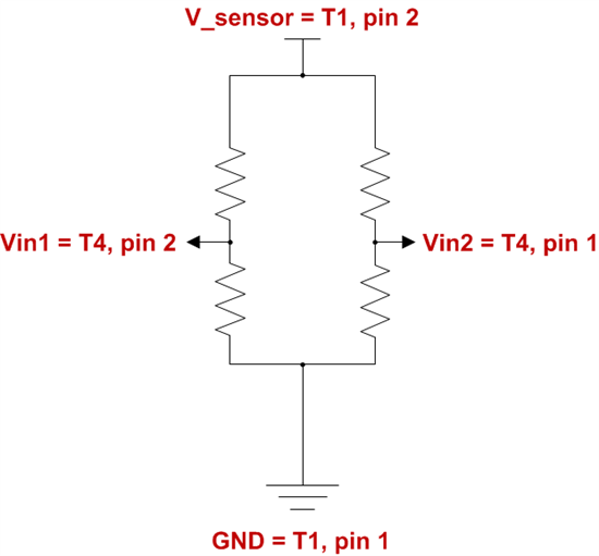
    Hardware connections:

    Software

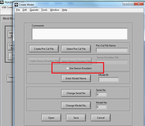
    • Same settings as before, but in the "Create Model" window make sure that "Use Sensor Emulator" is not checked.

    Operation

    • When prompted by the software, you must set the sensor to minimum, middle, or maximum output. You must also ensure that the sensor is at the correct temperature during temperature calibration, typically with an oven.

    Best regards,

    Ian Williams

  • hello.Williams

    thank you very much for your help patiently.i have done according those infromation.

    1.i do according your advise.but   i  want to know whether Register  and Block Diagram need setting before i set up Set up Cal and Auto Cal?.or there is relationship between Block and Set up Cal ,Auto Cal?

    2.there is no V_sensor voltage with T1 on my board.why?.i have done according those

  • hi.Williams

    could you  help to tack one problem.i can use Block Diagram to generate voltage in test mode .also can Calibrate real sensor use Auto-Cal  function.now the question is i can not set up  (include  Linearization Coef;Front End;Zero Dac;Gain  Dac; Output  Amp Gain) when  calibrate  sensor (there is no value in Analog Regster when Calibration) .so how can i put those  parameters into Analog Regster  before  calibrate?

    download file after calibration.there is no voltage output when i press the real sensor.