This thread has been locked.

If you have a related question, please click the "Ask a related question" button in the top right corner. The newly created question will be automatically linked to this question.

DRV110 minimum ON time

Other Parts Discussed in Thread: DRV110, DRV110EVM

Hello team,

Is there a minimum ON time sepc for OUT pin voltage on DRV110 device?

In one of the design I observed, as input voltage was increased, pulse width/frequency at OUT pin remained constant but it's peak value kept increasing!

Regards,

Mahendra Patel, TI

  • Hello Mahendra,

    I will ask the person responsible for support of this product to reply to your inquiry.

    Best regards,

    Jose

  • Hi, yes there is a minimum on time of 7.5% duty cycle as described in DRV110 datasheet at page 6. PWM waveform will vary from peak to hold current but will remain the same when in hold state. Its output level depends on input voltage.

    Best regards, Alain.


  • Thanks Alain.

    Regards,

    Mahendra.

  • Hi Alain,

    I agree that PWM will vary from peak to hold mode.

    However, in the hold mode itself, if we vary the input voltage, peak value of waveform across current sense resistor is changing (increases with input voltage).

    Can you please comment on this behaviour? This has been observed on DRV110EVM as well.

    Regards,

    Mahendra Patel

  • Hi Mahendra, this makes sense because I guess voltage input at solenoid level increases too, so peak voltage at sense resistor depends on it as well; but average voltage remains constant since Ihold is regulated.

    Best regards, Alain.

  • Hi Alain,

    We have observed a strange behaviour when we use 24VDC and 48VDC supply.During peak to hold transition, coil drop current drops and this causes coil to drop off as soon as it picks up.

    What do you recommend to resolve this issue? Shall we increase the pick time?

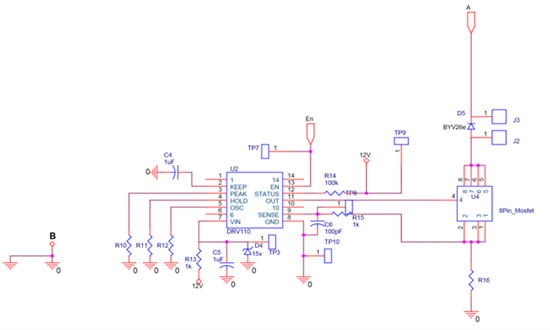
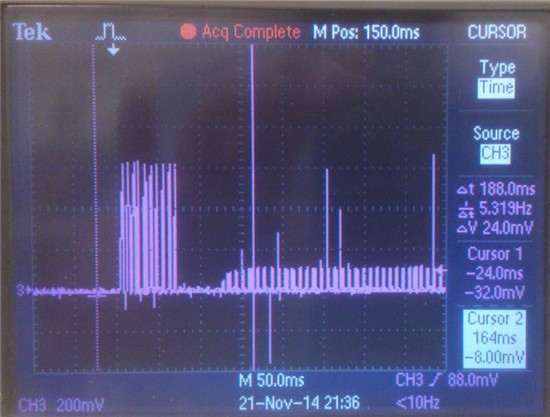
    Please find the wave forms and schematic attached.

    Thanks and regards, 

    Mahendra Patel

  • Hi Alain,

    Just to add to Mahendra's post, the coil's inherent pick-up time is 10-20ms, but the pick-up pulse duration as given by the DRV110 is set at 75ms in this case. Considering the above mentioned parameters, can you please help us resolve the issue?

  • Hi, sorry for my late reply as I was on vacations last week. I think the plot shows the voltage seen on R16 (sense resistor): is it right? Would you please tell me which component values you are using so I can duplicate this setup on my bench and verify it?

    Best regards, Alain.

  • Hi,

    Apologies for my late reply. You are right, the plot shows the voltage across R16(sense resistor). The component values used are Rsense=0.1ohm, Rpeak=100kohm, Rhold=150kohm and Rosc=180kohm.

    The coil(solenoid) details are as follows: L=5.86mH, R=19.32ohms measured at 1kHz frequency.

    Do let us know if you require any further data.

    Thank You.

    Regards,

    Premankar Choudhuri

  • Hi, thank you for these inputs!

    So in this case Ipeak= (1/0.1)*(900/100)*66.67=6000mA which I think is too big as serial resistance of the coil is 19.32 ohms. I have simulated this activation and at 24V input peak current is stuck at ~1.3A. You may try to either change the sense resistor or adjust the current to some lower value as anyway it should not reach this peak value assuming coil ESR is correct. For example Rpeak=450K for 24V case.

    Best regards, Alain.

  • Hi Alain,

    Thanks a lot for your inputs. We also tried to experiment the same settings of DRV110 with a coil whose resistance is 1.5ohms. The coil picks up fine but drops off after the pickup duration due to the issue of transition delay from pickup to hold on mode. If the plunger of the coil is pressed manually, it stays in hold-on mode. We would be needing such high currents(of 6A approx.) because of our high force requirements from the coil(solenoid) at such low voltages. The wire gauge used is 21 SWG. and it can carry that current safely. Using Rpeak=450K would result in a pickup current of 1.33A which is not sufficient for the coil to pickup.

    Your inputs please.

    Regards,

    Premankar Choudhuri

  • Ok, thanks for these explanations. I cannot reproduce this problem at my end so I would need some more info. Would it be possible to measure the current inside the coil itself using a current probe to see how it looks like? And would it be possible to measure the PWM waveform at OUT pin as well?

    Best regards, Alain.

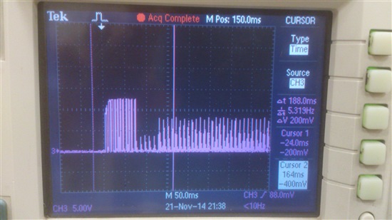
  • Referring to the above attached waveform image taken across R16(coil current sense resistor), I am attaching the corresponding PWM waveform at DRV110 OUT pin. Regarding the current inside the coil waveform, I shall get back in due course.

    Thank You.

    Regards,

    Premankar Choudhuri

  • Hi Premankar, according to this picture the VIN seems to collapse between peak phase and hold phase. Would you please capture VIN voltage at the same time so we can see how it behaves?
    Best regards, Alain.
  • Hello Alain,
    We suspected the same thing but did not observe any voltage dip at VIN during the transition. Still we shall try to recapture the waveforms.

    Thanks and regards,
    Premankar Choudhuri
  • Hi Premankar, you may measure it after the 1K resistor i.e. at VIN pin itself to see what's happening if possible. What may happen too is that the sampling frequency of the scope is not capturing adequately the peak voltage during the hold phase; if so you may change the time base to a faster value and delay the trigger to see how it looks like.
    Best regards, Alain.
  • I know this is an old forum entry, but I found this while searching for a solution to the same issue when using the DRV110 For solenoid Driving.


    The solenoid specifications are,


    Nominal Operating voltage = 110 VDC, Peak Current = 12A(Limited), Max DRV110 On time = 100 ms, Solenoid operating time = 40ms,


    I have based the same issue, when we turn OFF the signal to EN pin (After 40ms) when Vin has been powered to 100ms.

    Please refer the EN pin control schematic FYR.

    The Wveform, Green - Enable Pin; Yellow - Mosfet Gate (OUT pin) & Pink - Solenoid Current (1:1). Kindly Looking your Feedback on the same.

  • Elangovan,

    I am unable to see your pictures. Can you please put them into a ZIP folder and attach it? You can do this if you go to the Rich Text editor.

  • Dear James,

    Kindly clarify the reason for Malfunction in the EN & OUT (as well as source positive) during the turn OFF the pulse to EN pin (After the solenoid operates, Plunger Moves).
    Please find the Details below.

    Solenoid Series Resistance = 5.6 ohm; Nominal Operating Voltage = 120VDC; Total circuit powered ON time = 100ms & above;

    The solenoid (Plunger Moving) operating time = 40ms max

    Peak current limit is = 12A, Rsoc = 200k; Rpeak = 166k; Rhold= 85k; Ren=20k; Ckeep = 1uF  (Vales are Based on excel sheet Shared by Kevin in TI E2E Forum)

    When I have been Powered ON & OFF the entire circuit, DRV110 is working fine without any interrupt/Noise in the signals or Power Lines

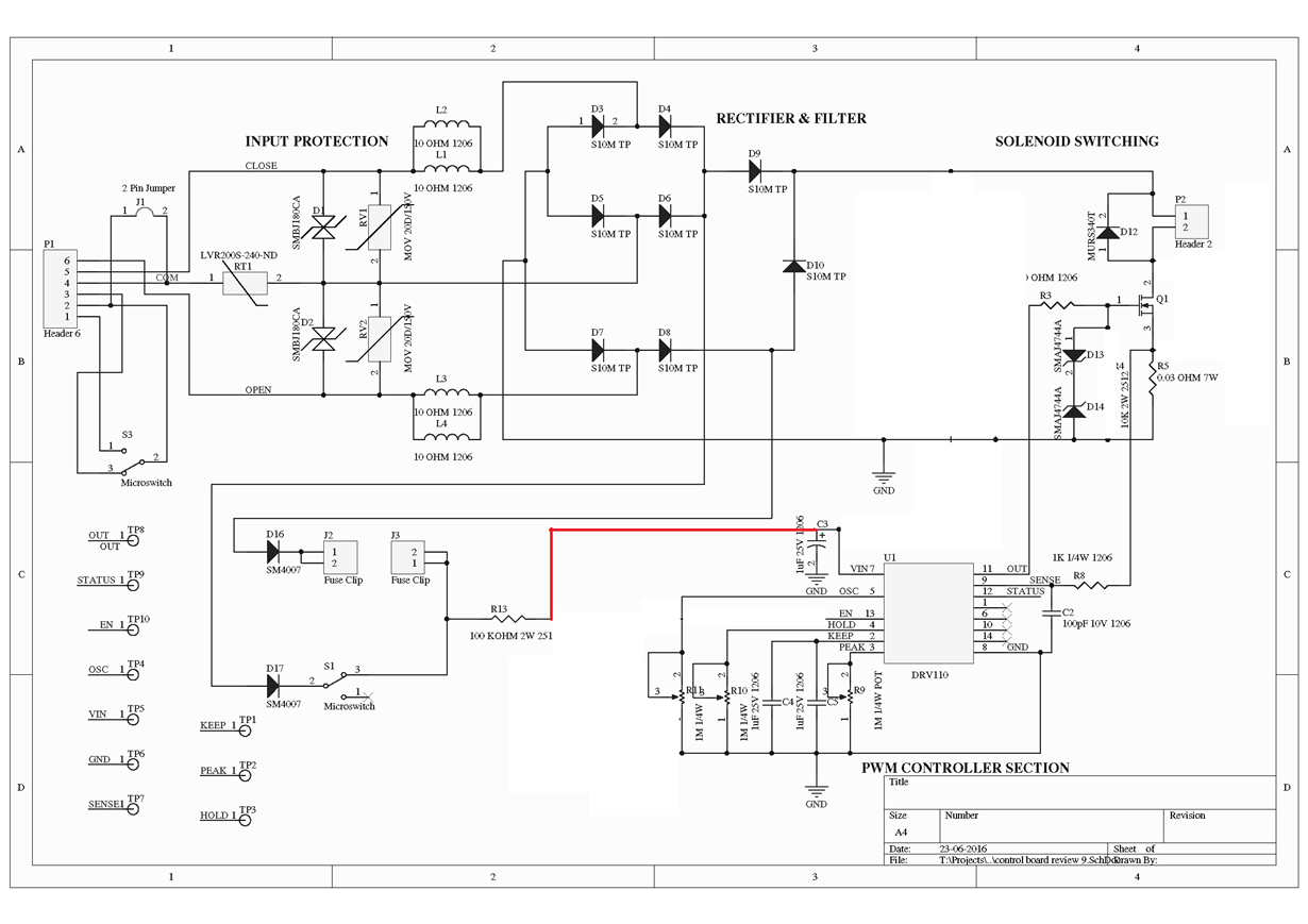
    But in the case, When I have been powered on the circuit for 100ms & the pulse to the EN pin would be break in after 40 ms (After Plunger Movement). When this happens we have notice that the hysteresis in the EN, OUT, Ckeep & Source. Kindly refer the attached waveforms, Schematic.

    Awaiting for your feedback on the same.DRV110.zip


    Waveform 1:


    Yellow - OUT; Blue - Ckeep; Green - EN; Pink - Solenoid current

    Waveform 3:


    Blue - Across the source voltage; Yellow - Across the 25mohm (Series in the source); Green - Plunger Position Detection o/p

    Waveform4:


    Yellow - OUT; Pink - Solenoid Current ; Green - Plunger Position Detection o/p

    Waveform5:


    Green - EN ; Yellow -OUT; Pink - Solenoid Current

    Waveform6:

    Green - EN ; Yellow -OUT; Pink - Solenoid Current

    Regards,

    Elango

  • Elango,

    Thank you for providing so many details in your response. They are helpful.

    I have some follow-up questions/troubleshooting suggestions:

    • What is the application of this device in your end equipment? Is it driving a solenoid, relay, valve, or other? How do you want to enable the DRV110 using the EN pin? The DRV110 has a 500 kOhm internal pullup resistor on the EN pin. If you want to energize your solenoid only when you power on the whole circuit, then you can leave that pin floating. If you want to control the solenoid using the EN pin, then you can use an open drain logic gate, a comparator, or just an N-Channel FET to drive the EN pin to ground when you want to turn the solenoid off. If you want to use 3.3-V logic from a microcontroller, you can use a 10 kOhm pulldown resistor on the EN pin.
    • What is the purpose of your R4 resistor? This will take current away from driving the gate of the FET. Can you remove it?
    • What is the purpose of the filter created by R6 and C1? I haven't seen this in other circuits. Can you please remove these for troubleshooting purposes?
    • Also, consider putting a capacitor or two between the output of diode 9 and ground.

  • Dear James,

    Thanks for the Input.

    The application is to drive the solenoid. At the current scenario, We are using an Current limit resistor + Zener diode for giving a pulse to EN pin & Leave it floating after the plunger Moved (With one pull down resistor). Whether current setup is not good in design/drive the EN pin?. Kindly Clarify to change the EN pin Driver circuit.

    As per your Instruction, I have removed the R4, R6 & C1 & tested the circuit. I have tested in three modes

    1. Remove the external control to the EN pin (R12, R13 & D15) & Control the VIN instead of EN through the Limit Switch S1 (Internal Pullup only for N pin - Refer Waveform 1

    2. Drive the EN pin using an Microcontroller Output with 10 pull down resistor (R13 removed, R12 - set as 10K) - Refer the Waveform 2

    3. Drive the EN pin from High voltage through a current limit resistor (R13 = 100K, R12 - 10K) - Refer Waveform 3DRV110_V02.zip

    In testing, I have set the Oscillator Frequency = 10KHz.


    From the test results, Please find the Noise/Interrupt in the EN pin during the case 1 itself. During the case 1, 2&3 the EN pin Behaviour has changing but there is no big difference in the Mosfet Gate Signal.

    Please clarify the same & Guide me in the Layout/Routing point of view.


    Regards,

    Elango

  • Elango,

    My suggestion is to connect VIN directly to R13 and leave the EN pin floating (see below). The DRV110 has an internal zener diode, but you may need to resize R13 and C3 if you want to use it. Alternatively, since this is powered from a 120-V supply, you could also copy the VIN supply part of the circuit from http://www.ti.com/lit/ug/tidu584/tidu584.pdf

  • James,

    Thanks for your suggestions. The same (Modified circuit Which you have shared) I have experimented  & shared the waveform of EN, VIN & OUT pin in the last conversation. I will attach the same again for your reference. You can find the noise/interrupt in the EN pin after I left the pin in Floating. Please clarify the reason for the same & looking your input on the Layout/Routing point of view.3377.DRV110_V02.zip

    Regards,

    Elango

  • Elongo,

    As far as I can tell, your layout is fine. Just make sure that all the passives are as close as possible to the pins of the DRV110. I see now from your previous post that you had tried my suggestion.

    Now that I am looking again at your scope shots, it looks like VIN is dropping out (VIN=yellow trace, correct?), which will cause the part to turn off before it goes to the hold state. Do you know why VIN drops out? Here are some more troubleshooting suggestions:

    1. In your system, power VIN and your solenoid directly from a lab supply. Does the issue occur now? This will help us determine if the issue is with the DRV110 or the power circuitry. You can also power your solenoid and VIN separately, using the power circuitry for one and the lab supply for the other. Try both combinations here. 
    2. Probe various points along your power circuitry to determine where the source of the issue is.
    3. If the above solutions don't help, send me a private message with your contact information and we will discuss next steps we can take to resolve this issue.

  • The solution to reduce noise on the EN pin is to put a 10uF capacitor after the bridge rectifier and 10 pF cap from EN pin to ground.