This thread has been locked.

If you have a related question, please click the "Ask a related question" button in the top right corner. The newly created question will be automatically linked to this question.

PGA309 Multi-Cal-System problems by reading from agilent

Other Parts Discussed in Thread: MULTI-CAL-SYSTEM, PGA308, PGA309, XTR115

Dear Mr Williams,

we use the folowing board and software:

Concerning : Problems with implementing Multi-Cal-System

 board:

1. USB-DAQ-Platform 6490801 PWB-C

2. Multi-Cal-Master 6507943 Rev F

3. Multi-Cal-Interface 6507946 Rev D

 and software:
Multi_Cal_PGA308 Installer 2v1 (WindowsInstaller-KB893803-v2-x86.exe)

Windows XP

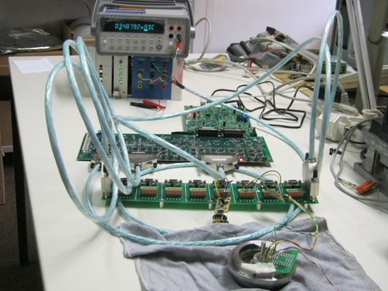
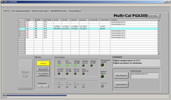
The test construction was as carried out as in the suitable user manual is described and is illustrated. We have in addition also from Texas suggested the Agilent 34401A multimeter connected by RS-232 (on COM1). We have done all settings for current loop mode like described in the user manual. By pressing the "Do Cal" button the automatic Scan performs perfectly. In the next step the system are trying to read the minimum value. On this occasion, an error is announced and the calibration is faulty.


This is our test setup with a real (5000 Ohm 1mV/V) presure sensor.

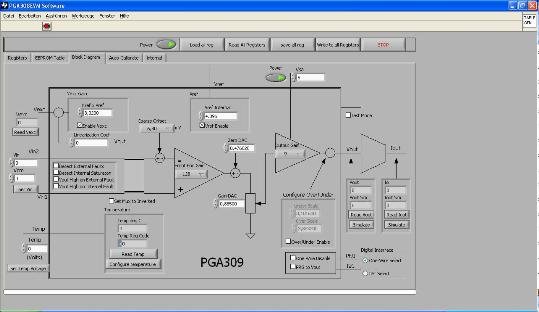
If we connect the PGA309 to EVM-Board, you see the parameter above. On minimum stimulation of the transducer

we get the offset of 4mA and if we stimulate the Transducer to maximum we get 20mA. This is o.k. ,but we don't get

this result by using multi-cal-system.

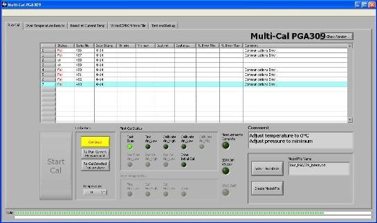
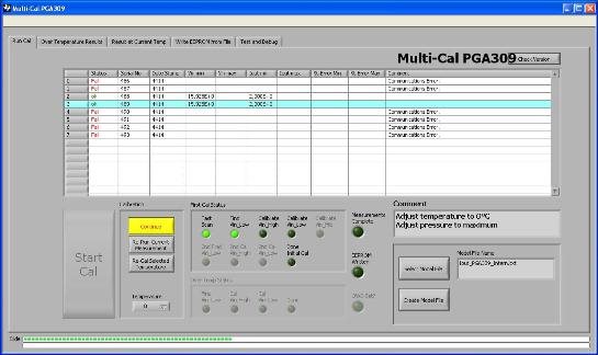
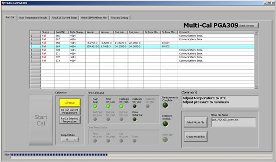
This is the first scan of PGA309-Module. This run is o.k. , because there are only two module connected to the system.

But during this step (the multi-cal-system perform a call to agilent multimeter to get the mA value) the wrong

values for "Iout min" are read by the software.

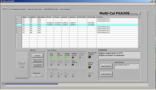
This are the results for channel 2 and 3 (the register setting is wrong)

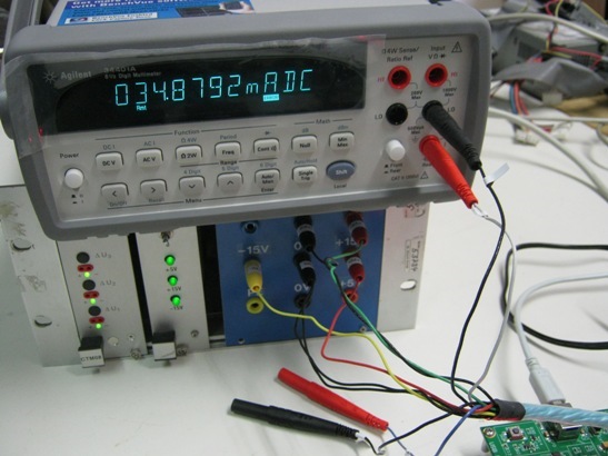
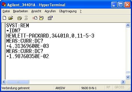
This value for minimum and maximum are read directly by using Hyper Terminal programm.

This reading is correct, but not in the multi-cal-system !


With best regards

Christian M.


  • Hi Christian,

    Unfortunately, the engineer who normally supports this product is traveling internationally at the moment. I have asked him for any suggestions he might have on why the multi-cal software would read values from the multimeter incorrectly and I will update this thread when he responds. 

  • Hello Christian,

    Thank you for your patience.

    First, I recommend downloading and installing a new beta version of the Multi-Cal PGA309 software. There are numerous bug fixes in this version which may resolve the issue easily.

    ftp://ftp.ti.com/pub/linear_apps/Multi-Cal-PGA309/Multi_CAL_PGA309%20Installer%202.1.zip

    Second, can you please verify that you are connecting the +VDUT and -VDUT plugs of the power cable to a loop power supply which is floating relative to the ±12V supply? If not, then you will measure incorrect and high current values such as the 35mA in your photo.

    Best regards,

    Ian Williams
    Linear Applications Engineer
    Precision Analog - Op Amps

  • Dear Mr Williams,


    many thanks for the response and the new program version. I have uninstalled the old version

    and have installed the new one, however, the new version displayed the same version information

    as the old version.

    The results seem to be same as by the first program version.

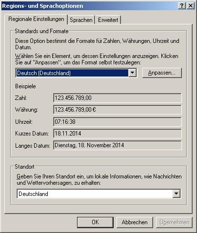
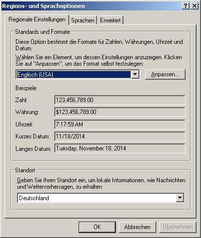
    Then I have set the language of the Windows-XP system from GERMAN to English-US language.

    The dot and the comma are exchanged there.

    At this moment the internal readings and calculations seem to be correct.

    This reading from the Agilent 34401A are correct. It is exactly the same value as on Agilent Display.

    But there must be another fault. The start value is set to 12mA, but in the precal-file the value is

    set to 4mA ??

    This result are looking quite better than before.

    I have checked the supply device. These are two independent insertion power supply units.

    The output voltages from each power supply are not internal coupled galvanically.

    Best regards,

    Christian M.

  • Hello Christian,

    The dot/comma error was definitely a problem - good catch by switching the language settings. We will need to consider that as a future software improvement.

    Are you saving a new pre-cal file with 12mA as the low target? Can you attach your most recent pre-cal file?

    Best regards,

    Ian Williams

  • Dear Mr Williams,

    No, I have taken over the available PreCal and model file from the previous program version.

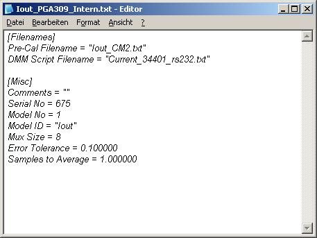
    Here is the MODEL-File for our current mode application:

    The same file in text form:

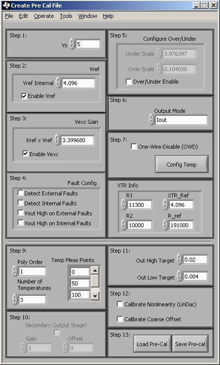
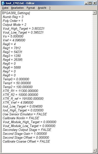
    and here is the PreCal-file:

    the same file in text form:

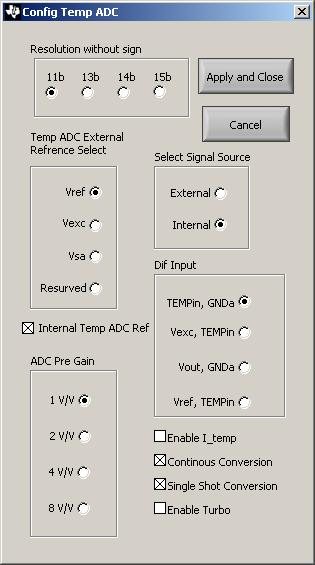
    and this is the temperatue setting option:

    Many thanks for helping to solve the problem.

    Best regards,

    Christian M.

  • Hello Christian,

    Your Pre-Cal settings in Step 11 have the IOUT target as 0.004A (4mA) minimum and 0.02A (20mA) maximum. If you wish to have 12mA as the minimum, you should adjust the Pre-Cal file. It seems that the software is functioning correctly.

    I recommend changing settings in Step 12. Check the boxes for "Calibrate Nonlinearity" and "Calibrate Coarse Offset" in order to better correct for your sensor errors.

    Finally, I also recommend changing the Temp ADC resolution to 15 bits for higher temperature compensation accuracy.

    Best regards,

    Ian Williams

  • Dear Mr Williams,

    the Pre-Cal-Settings in step 11 are wanted thus.
    I want the minimum of 4 mA and the maximum of 20 mA, but the software try to set 12 mA on minimum

    although I have not set this.

    Many thanks for the tips:

    I have set Temp-Resulution to 15 bit.

    I have set the "Calibrate Nonlinearity" and "Calibrate Coarse" option in step 12.

    ... but the result is nearly the same as before.

    Here is the modified Pre-Cal-File:

    and this is the modified Config-Temp-File:

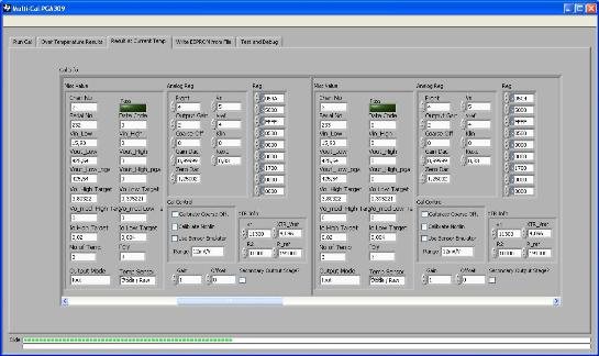
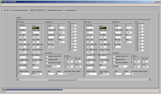
    this are the result of the settings:

    and this is the associated Cal-Info-Setting:

    Please have a look on device number 2, this is my DUT (the sensor on device 3 was not stimulated and is always remain on minimum)

    The connected sensor (device 2) is a 5000 Ohm bridge (960uV/V). I have measured the FSO = 3,18mV (stimulated to maximum). I think the back calculated values are to high ??

    Best regards,

    Christian M.

  • Hello Christian,

    Your pre-cal file is correct, and the target output current is set from 4mA to 20mA. You can see this in the "Io High Target" and "Io Low Target" fields in your last screenshot.

    The first step of calibration is to set the system output to roughly mid-scale, or 12mA. This allows the input signal to be back-calculated while reducing the possibility of errors due to output saturation. It also provides for the largest range of gain and offset adjustment options during calibration.

    I think the error is coming from elsewhere. The input values are too high, as you've observed. The software back-calculates the input based on the PGA309's internal gain and offset settings, but it also depends on the resistor values in the "XTR Info" section of the Pre-Cal file window. These resistors convert the PGA309 output voltage to an input current for the XTR, and must match the resistor network on your PCB.

    See this application note for a detailed explanation of the standard resistor network used in this application: Using the XTR115 with the PGA309 to Generate 4mA to 20mA Output

    Best regards,

    Ian Williams

  • Dear Mr Williams,

    many thanks for the helpfull information about the mid-setting of multi-cal-system and the application note. I don't use the 2.5V reference output from the XTR115, instead i use the 4.096V reference output (pin 16 of PGA309)  from the PGA309. It is the same circuit as on the PGA309 TEST BOARD. The resistor values are the same. The real word voltage value at the output of the PGA309 are measured by 0.39543V --> 4mA and 3.67356V --> 20mA. These value are nearly similarly to the calculated values in the cal-info table.

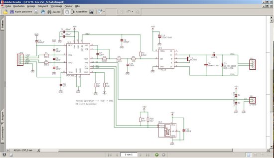
    This is our schematic:

    Best regards,

    Christian M.

  • Hello Christian,

    I don't see any issues with your schematic. At this point I have no further recommendations for you to test. It's possible that there is a problem with the setup or a setting in the software.

    The most efficient way to resolve the issue is to send me one or two of your PCBs. I will test them here on the Multi-Cal system and should be able to quickly identify the root cause of the problem.

    I will contact you outside the forum to provide my shipping information.

    Best regards.

    Ian Williams