This thread has been locked.

If you have a related question, please click the "Ask a related question" button in the top right corner. The newly created question will be automatically linked to this question.

OPA 454 not working; burning out

Other Parts Discussed in Thread: OPA454

Hello,

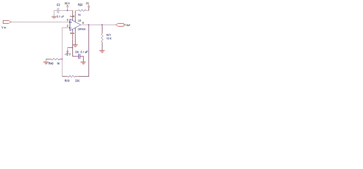
OPA 454 is connected as per the circuit for generating a 0 to 50 V output. V in  is connected to a DAC having a voltage range from 0 - 3.3 V.

Also the power pad is connected to -12 VDC. But OPA 454 is getting burnt within some time.

Is there any problem in the connection, please help.

Also the 50 V and -12 V is used by some other circuits.

Regards,

Anish

  • Hello Anish,

    Your circuit connections to the OPA454 look appropriate, so something else in the system must be causing issues.  Please help answer the questions below and we'll determine the issue.

    What type of load is connected to the "VOUT" net on your schematic? Is there any capacitance or inductance connected to this node?  Does the OPA454 function as expected before it burns up?  Does the OPA454 temperature steadily increase while operating before it burns up, or does it suddenly fail?  Finally, does the OPA454 burn up at room temperature or at an elevated operating temperature?

  • Hello Collins,

    Thank you for your response. Please go through the answers.

    What type of load is connected to the "VOUT" net on your schematic? Is there any capacitance or inductance connected to this node?  

    Right now a resistive load of 3.3K is connected to VOUT. There is no capacitance or inductance in this node. But the application is intended for inductive load in future. 

    Does the OPA454function as expected before it burns up?

    We are not getting the desired functionality for the OPA454. It is getting burnt within some time ( approx. 2 minutes)

    Does the OPA454 temperature steadily increase while operating before it burns up, or does it suddenly fail?  

    Temperature is not getting increased. It gets burnt within 2 minutes approximately. We have replaced the ic for the second time and the failure is of same nature.

    Also the track to the 7th pin of OPA454 is getting burnt in both cases.

    Finally, does the OPA454 burn up at room temperature or at an elevated operating temperature?

    It is in room temperature.


    Meanwhile we will check whether any other circuit is having any effect on this. Please reply any points to be checked.


    Thanks and Regards,

    Anish


  • Hi Anish,

    I just wanted to confirm that you have been soldering the powerpad heatsink to the PCB as well. I noted in the datasheet that:

    PowerPAD is internally connected to V–. Soldering the PowerPAD to the printed circuit board (PCB) is always
    required, even with applications that have low power dissipation.

    It was mentioned in small print below the pinout, so it could easily have been missed. This could also account for the burnout.

    -Josh
  • Hello Joshua,

    Thanks for the comments! 

    Anish,

    Thank you for providing additional information about your application.  We're still not sure what's causing the issue but have a few other comments/questions.

    First, be sure you're using capacitors with the proper voltage rating (>50V) for the V+ or they may be burning up.  This shouldn't affect the OPA454 but it would affect the PCB. 

    Second, what are you connecting to the "STATUS FLAG" pin of the OPA454?  The connection was not shown in your schematic.

    In your answer to the question below, can you please clarify whether or not the OPA454 was outputting the correct voltage based on the DAC input voltage before the failure occurs at around 2 minutes of operating time?  The output voltage should be the DAC input voltage multiplied by the non-inverting gain.

    Does the OPA454function as expected before it burns up?

    We are not getting the desired functionality for the OPA454. It is getting burnt within some time ( approx. 2 minutes)

    Based on the information you've provided so far and the visible damage to Pin 7 of the OPA454 our initial suspicion is that something in your system is causing a voltage transient on the V+ or the output pin resulting in the electrical overstress damage that you're experiencing.  Is there any reason that the absolute maximum power supply voltage of 120V would be exceeded, even momentarily?  Would anything in the system cause the output pin to experience a voltage outside of the power-supply voltages?  What are you using to generate the power-supply voltage for the OPA454?

  • Hi Joshua,

    Power pad is soldered to the pcb as well. We have re-ensured it by keeping the blower over the ic.  

    Regards,

    Anish

  • Hi Collins,

    First, be sure you're using capacitors with the proper voltage rating (>50V) for the V+ or they may be burning up.  This shouldn't affect the OPA454 but it would affect the PCB.

    We are using the through hole disc capacitors and it is having greater than 50V rating.

    Second, what are you connecting to the "STATUS FLAG" pin of the OPA454?  The connection was not shown in your schematic.

    In the status flag there is no connection.

    In your answer to the question below, can you please clarify whether or not the OPA454 was outputting the correct voltage based on the DAC input voltage before the failure occurs at around 2 minutes of operating time?  The output voltage should be the DAC input voltage multiplied by the non-inverting gain.

    For the first two times (When the ic's got burnt)  we are not having any output on the OPA454 w.r.t. the DAC input voltage. We doubt while soldering the power pad the blower might have over temperature (300 degree C was the set temperature of the blower). How much should be the approximate temperature while soldering the power pad? 

    Fortunately for the third time with the new ic, OPA454 is having the desired output voltage and is working satisfactorily for the time we tested. We will test it for more time.

    Is there any reason that the absolute maximum power supply voltage of 120V would be exceeded, even momentarily?  Would anything in the system cause the output pin to experience a voltage outside of the power-supply voltages?  What are you using to generate the power-supply voltage for the OPA454?

    We will check whether there is a possibility for voltage transient or over voltage, even-though the chances are rare.

    We are using a SMPS based power supply to generate 50 V, 5 V and a transformer based supply to generate -12V and the grounds are tied together.

    REgards,

    Anish

  • Hi Anish,

    Based on the power supply configurations you've listed, it's possible that the power supplies are coming active in a way that may place the OPA454 into an unknown state resulting in the failures/damage you're experiencing.  We recommend that you place transient voltage suppressors on the power supplies to provide a known conduction path for the power-supply currents in all conditions.  This information is shown in the short attached presentation as well as the TI Precision Labs ESD and EOS video series that you can access from this link:  

    Use a +50V TVS for the V+ pin and a -12V TVS for the V- pin.

    6888.Op Amp Power Sequence.ppt

  • Hi Collin,

    Thank you for the informative. Will accommodate the changes.

    I am not able to access the video series link.

    Regards,

    Anish

  • Hi Anish,

    Let us know if you still experience issues after the suggested modifications.

    Try this link instead: www-uat.itg.ti.com/.../precision-amplifier-precision-labs.page

    If it doesn't work would you post an image of the error message?

    Thanks!
  • Hi Collins,

    We will let you know if the problems persists after the suggested modifications.

    Thank you.

    REgards,
    Anish N