This thread has been locked.

If you have a related question, please click the "Ask a related question" button in the top right corner. The newly created question will be automatically linked to this question.

Problem of TL074's 0V input

Guru 19485 points
Other Parts Discussed in Thread: TL074

TL074's supply voltage timing is "Vcc+:15V → 5ms delay → Vcc-:-15V" because of customer reason.

Is it no problem?

Is there problem and inprovement point, please let me know.

Concern point is below.

・Common Mode Input Votage Range:±11V_min,

  When supply only Vcc+:15V, Input voltage range is 4V~11V.

 I think that TL074 will error on VIN:0V.

・In the past, the other OPAMP used only Vcc+:15V,

 VIN:0V supply became nearly -15V.

 I worry about whether the same thing will happen.

Best regards,

Satoshi

  • Satoshi san,

    It is highly recommended that no inputs are shorted to ground. A series resistance on the inputs is high recommended.
    The reason is that the -15V might become positive during power up or power down sequence.
    A grounded input might have high input current when -15V supply is positive voltage.

    During the time that only +15V is present, the device may or may not be performing to application design depending of things like input common mode range. Once the -15V also comes online then normal operation should begin.
  • Ronald-san

    Thank you for reply.

    Sorry for addition, please let me know three point below on problem case (timing:15V→-15V).

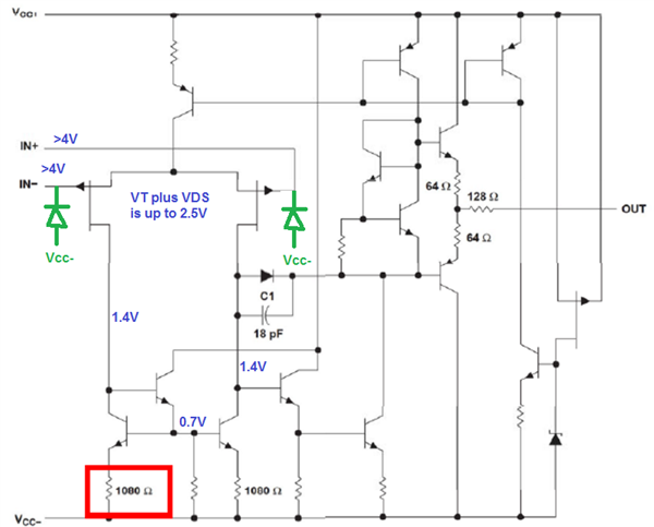
    ①I think that the route of inlush current is "VCC- ⇒ IN-", is it correct?

    ②When circuit is voltage follower, is it problem,too?

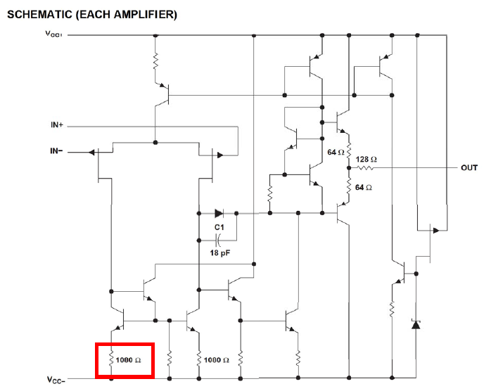
    ③Can internal resister (please see below) moderate this problem?

    Best regards,

    Satoshi

  • Satoshi san,

    The VCC- to IN diode is parasitic and shown in green. This is the current path.

    The reason that input must be >4V more positive than VCC- is shown in blue.