This thread has been locked.

If you have a related question, please click the "Ask a related question" button in the top right corner. The newly created question will be automatically linked to this question.

LM311 Zero Crossing Detector

Other Parts Discussed in Thread: LM311, LMV358

Dear Support,


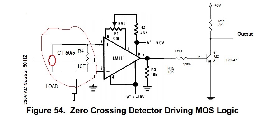
We are trying to detect Zero Crossing Detection of Voltage (V) and Current  (Amp ) with LM311. I have referred Document SNOSBJ1E Figure 54 Circuit as below. Is it right method to connect CT for Zero Crossing Detection ? 

The problem which i have faced,  I am  not getting V and I in phase ( with no phase delay) at Load(100W Bulb) at output of Zero Crossing  Voltage and Current using Dual Channal CRO. 

Please Suggest what i am doing wrong ?

--

Gurpreet

  • Gurpreet,

    As drawn, the non inverting input (pin 2) is floating and has no signal.

    One side of R4 should also be at ground.

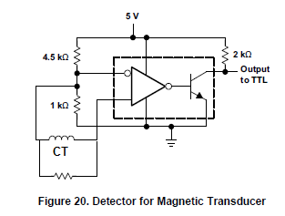
    The extra inverter  using Q2 is not needed. If phase need reverse then swap CT leads.

    The usage for pins 7 and 1 are not good to drive a NPN base.

    Try this modified figure 20 schematic instead. It needs only one supply.

  • OK.

    Thanks for Comments,

    Will it work for Voltage ZCD also ?

    Actually I want to measure Vrms and Irms and ZCD of V and I .

    Please Suggest ..
  • Gurpreet,

    To get Vrms and Irms you will need an analog readings for both current and voltage.
    I don't see how ZCD will help you.

    To you plan to use hardware or software to convert real time data into RMS?
  • Ron Michallick,

    Thanks for your valuable Comment,

    I have to do four task in Once Project . 

    1)  Voltage (RMS)

    2)  Current (RMS)

    3)  ZCD (V)

    4)  ZCD (I)

    I am using 10-Bit ADC based micro-controller  to convert real time data into RMS. ZCD (V) and ZCD (I) is for measure Phase angle to measure Power Factor

    Domestic and Industrial Load (Induction Like Motor). Please Suggest LM3xx topology or design to measure  Voltage and Check ZCD(V), and Current RMS

    and  ZCD(I) with Single CT

    --

    Gurpreet 

  • Gurpreet,

    Attached is a circuit in development for LMV358 current transformer amplifier. The concept can be used for other amplifiers. A simple amplifier can be used for transformer output because the output is isolated and doesn't pass DC. A differential amplifier is not needed. Only the last amplifier will contribute to a DC error. Bandwidth is 10Hz to 500 Hz.

    For line voltage measurement use a differential amplifier with attenuation. High input resistors and low feedback resistors. There are safety concerns when attached to line voltage. I can't help you with that.

    Comparator(s) after the amplifier could be use for zero crossing or simply to designate the start and end of cycle. Software could correct for DC errors and determine when the zero crossed (for both signals) if desired.

    CT LMV358 2x filters.TSC