This thread has been locked.

If you have a related question, please click the "Ask a related question" button in the top right corner. The newly created question will be automatically linked to this question.

Select the right comparator (if it exists at all)

Other Parts Discussed in Thread: OPA2197, TLV1702, TPS62177, OPA2365, TINA-TI

Hi

I am a bit overwhelmed with the number of comparators on the market. I therefore hope someone can point me to the right device....

Here is the signal I have:

A power amplifier delivers the +/- 18V pulse width coded signal to the load (232µs=0, 116µs=1). After the end of a packet the amplifier does a shutdown for 450µs. In this time the load will send a 250kBaud message  (the red part) by forcing a 35mA current (+ or -) on the line.

It is this current I Need to detect by a Windows comparator an send the result to an UART.

Now, what people normally do, they put a 1.5Ohm shunt resistor in the line and in parallel 2 antiparallel diodes. So they can detect the 35 mA and the high currents can pass through the diodes. But this does not allow to measure the currents 0..4 Amps to the load - which I need to do.

So I could put a 0.1Ohm shunt resistor on the line and use an ADC the measure the current to the load (regular current between 20mA and 3A, as well as overcurrent e.g. 5A). This would result in a acceptable voltage drop and allow for a 0.5W SMD resistor. So far so good. But the window comparator would only get a + or - 3.5mV signal.
hmmm....

By the way, the supply is 3.3V, taken from the +/- 18V signal and I Need to do this for 2 channels. So I selected a 2 channel UART with ‘enable’ and I2C interface as well as 2 channel ADC with I2C. The microcontroller will need to transmit the UART and current results via WLAN.

So what comparators could do the job????  

Thanks in advance for any help..

Thomas

  • Hi Thomas,

    I am not sure I understand every detail of your circuit so please correct any misunderstanding I may have.

    A window comparator has the Vin input which would accept the +/-3.5 mV, and the VHI upper threshold and VLO lower threshold inputs. Those would be set as reference levels where the window comparator switches state. It appears you need the comparator to switch state when the voltage across the shunt exceeds either -3.5 mV, or +3.5 mV. If that is the case, the VHI and VLO levels on the pins would have to be a little less than -3.5 mV and +3.5 mV, respectively.

    When the signal goes into the +/-18 V mode, then the window comparator would still make a comparison. Even if you don't need the information. The issue here is that the input level to the comparators would be a high voltage so a high-voltage comparator would be needed. The fact that you have +/-18 V available would be useful for the supplies.

    A high-voltage dual comparator such as the TLV1702 would work if the reference voltage levels weren't so low. Its voltage offset can be as high as +/-3.5 mV, which is right in the range of the levels you need to compare. An alternate approach is to use a high-voltage op amp as a comparator, but it can't be just any op amp. It needs to have a rail-to-rail input range, low voltage-offset, and no input-to-input clamps. A possible candidate would be the OPA2197. You can see the datasheet here:

    One issue when dealing with such low reference levels is noise. Any external noise that couples into the comparator circuit could really be a problem. You might be able to apply a small hysteresis to improve the noise immunity.

    Regards, Thomas

    PA - Linear Applications Engineering

  • Hi Thomas

    First, thank you for your quick answer. Here comes some clarification:
    The signal I am interest in goes from 0 to +3.5 mV (or from -3.5 to 0V, if to current polarity is reversed). It is a 250 kBaud serial signal.
    Before and after that period is a small (I think it was 40 µs) 0V break. The current before and after that would be limited to 5 Amps, so a max. voltage of +/- 0.5V would hit the comparator. What the comparator delivers outside the (red marked) period is not of relevance. The microcontroller will decode the period before and after directly and will detect the end / beginning of the +/- 18V period. It will then enable the UART on the comparator output to catch the serial message.

    The 3.3V power comes from the +/- 18v using a TPS62177 (which I already used - with the help of an E2E engineer - in another project).

    Maybe I could increase the shunt to 1.5Ohms so the signal would increase to 5.1mV. So either a value below -4mV or above 4mV should drive the output of the comparators to 0.
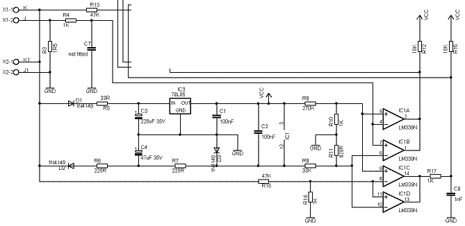
    Here is a sample how other people do it. All designs I have seen so far are more or less limited to 1 - 2 Amps. For higher currents their components will heat a lot and get quit big. (X1 is input (left in my previous Picture), X2 Output). With the diodes D2 and D3 they build the negative supply for the comparator, which I think I could do as well. The second pair of comparators is used to detect the phase where there is 0 volts on the input and therefore the current signal is expected from the output side.

    My intension (maybe wishful thinking) is to end up with a board less than 30 x 40 mm for 2 channels.
    I think your suggestion to use an op-amp is what I need. I just don't understand how I would have to design them in and how to interface the 2 op amps to the UART.....
    I hope you can help me find a solution.

    Best regards

    Thomas

  • Thomas,

    Why not have two current senses?
    When driving the load use a low resistance sense in the driver.
    During the "cutout time" the driver should be high impedance.
    Use a larger resistance to easily detect the current flow as a 'large' voltage.
    If desired you can switch the large sense resistor in and out as needed.
  • Hmmmm......
    switching the resistor. This would require a switch that is capable of carry 5 Amps or in case of a short circuit in the load (which can happen) even more...SO, a big switch then.
    so I might end up with the usual design: 1 or 1.5 Ohm shunt and 2 antiparallel diodes over them. This allow to measure small currents, but forces me to add a second chip for the current limit (5A).
    Thank you anyway for the input.
    Best regards
    Thomas

  • Hi Thomas,

    I am still working on this and running simulations on some ideas, but haven't cracked it yet. I'll report anything I come up with.

    Regards, Thomas

    PA - Linear Applications Engineering

  • Great news. Thanks.

  • Hi Thomas,

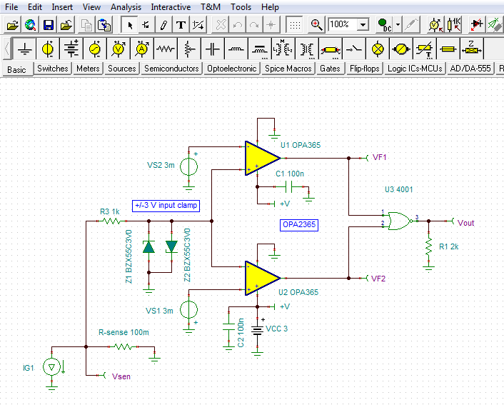
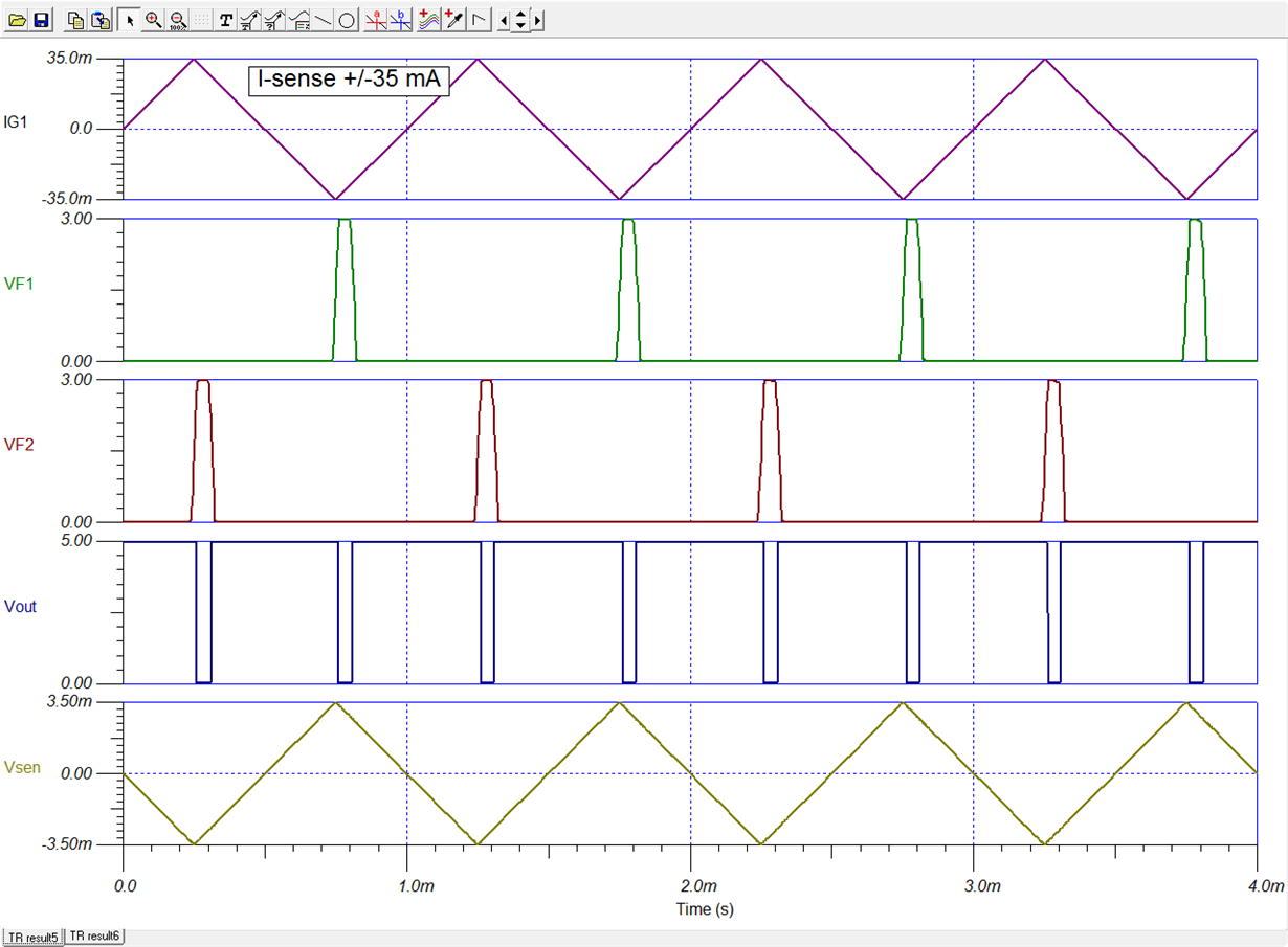
    Please see the current sense circuit below. A fast OPA2365 CMOS dual op amp is configured as a window comparator. The window comparator is followed by a CMOS NOR gate which results in the output going low when the comparison level is in-between the lower and upper reference levels. The reference levels were set to +3 mV and -3 mV so that when the current exceeded +30 mA and -30 mA the output state would change state. A NAND gate could be used if the output state needs to be the inverse.

    The output only changes state when the input is in-between the two reference levels so the dwell time can be short if the waveform has fast edges. The triangle wave used in the simulation has a slow rise/fall time and its dwell is longer with low current levels such as +/-35 mA, when compared to +/-3 Amps. The dwell could be very short for a square wave having fast edges.

    I have attached my TINA-TI Spice simulation circuit if you wish to run simulations.

    Regards, Thomas

    PA - Linear Applications Engineering

    OPA2365_wind_comp_01.TSC

  • Thank you Thomas for your support.

    I will try that and hope that there is not too much noise....

    Best regards

    Thomas