This thread has been locked.

If you have a related question, please click the "Ask a related question" button in the top right corner. The newly created question will be automatically linked to this question.

DRV101 solenoid driver problems

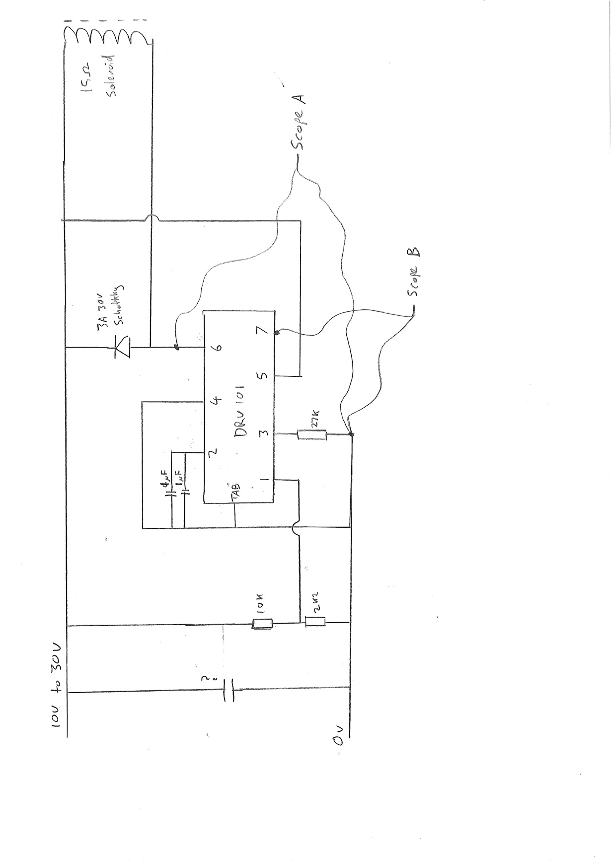
I am using a DRV101 to drive a 15 ohm solenoid connected as shown below.20160912175002176.pdf

Vcc = 14V

CD = 2uF

R = 27K (gives 26.8kHz pwm)


After this has been in PWM mode for around 15 minutes the device appears to breakdown. The device does not get hot and has a large heatsink fitted. Can anyone help please?


Screen shots are below. Blue is pin 6 (output) to GND, red is pin 7 (flag) to ground).

screenshot1.pdf


  • Good evening Mr Dunton, I would like to know what voltage you have in pin 7 of DRV101? because you could use it to see if you have a fault.

    Normally high (active low), the Flag signals either an over-temperature, over-current, or under-current fault. The over/undercurrent
    flags are true only when the output is on (constant dc output or the “on” portion of PWM mode). A thermal fault (thermal
    shutdown) occurs when the die surface reaches approximately 165°C and latches until the die cools to 150°C. Its output
    requires a pull-up resistor. It can typically sink two milliamps, sufficient to drive a low-current LED.

    Please, let me know
  • The red trace on Screenshot 1 above is the pin 7 flag output. This remains at 3.3V throughout and does not change. Pin 7 is connected to 5v via a 5K6 resistor and an LED. See attached.20160912175002176 - with LED + scope.pdf


  • Good morning, I see.

    In your drawing I didn´t see where pin 1 is connected, could you tell me how that pin is connected?

  • I have left pin 1 unconnected. In the datasheet it said that it would quickly rise to the activation level if left unconnected. It also said that it can be momentarily connected to Vcc, but can this be permanently connected? I am testing this at Vcc = 14V at the moment but eventually need this to operate in the range Vcc = 10V to 30V.


    I have also tried connecting a 1uF tantalum capacitor and 22uF aluminium film capacitor between Vcc and GND. This has produced a cleaner square wave although there is still some undershoot. See the screenshot2 below with the capacitors connected.

    screenshot2.pdf


    The breakdown still occurs with these capacitors and also still occurs if I substitute the solenoid for a 15 ohm or 100ohm resistor.

  • Ok, Mr Dunton, this information is about Pin 1:

    The input is compatible with standard TTL levels. The device output becomes enabled when the input voltage is driven above
    the typical switching threshold, 1.7V. Below this level, the output is disabled. With no connection to the pin, the input level rises
    to 3.4V. Input current is 20µA when driven high and 80µA with the input low. The input may be momentarily driven to the power
    supply (VS) without damage.

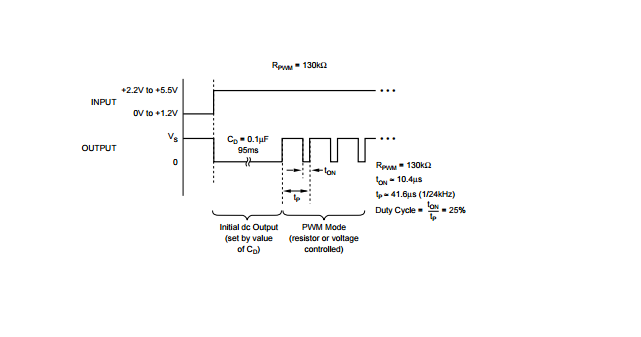
    The Input (pin 1) is compatible with standard TTL levels. Input voltages between +2.2V and +5.5V turn the device output on, while pulling the pin low (0V to +1.2V), shuts the DRV101 output off. Input current is typically 80µA.

    Could you try a voltage between +2.2V and +5.5V in Pin 1, please?

    The device output will be working while you have that voltage in pin 1.

    If you have it unconnected that pin could take some values randomly and that voltage is lesser than 1.2V, the device output will be off, I´m sure If you measure voltage in PIn 1 when you output is off, you will have a voltage lesser than 1.2V.

    You are right, you can connect that pin to VS directly but for short time, please do not connect it to VS for a long time.

    Voltage in Pin 1 (+2.2V to +5.5V)

    Please, let me know if you could solve your problem
  • I have tried applying 5V to pin 1 but unfortunately that did not solve the problem. I have also tried swapping the device with another DRV101 but that had the same problem.

    I have attached screenshot 3 showing the trace between pin 7 (flag) and GND when in PWM mode. Is that any help?

    screenshot3.pdf


  • Could you show me your complete drawing including the connections to Pin 1?

    Are you using a PCB? I would like to check it .

  • I have it on a breadboard. The circuit diagram and photos are below.

    The 5V is supplied direct from a 7805 voltage regulator.

    Breadboard diagram.pdf

  • If you had a fault condition, you would have its Flag output is driven low (pin voltage typically drops to 0.3V).

    According to your last screenshot, you have about 20mV in Pin 7.

    Before you had it high (normally working) 

  • I see.

    When we use Breadboards, we could have some problems due to capacitance, resistance by faulty contacts, in high frequency would be worst, oscillations, and so.

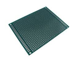
    I would advise you to use a Perfboards, if you can do it, I think you can solve that problem in your circuit.

    If you have unconnected Pins, those could take randomly values, even more if you use a Breadboard.

    Please, let me know when you do something.

  • Having disconnected everything and completely reconnected it on the breadboard, I have had it switched on like this for the past hour and it seems to be working ok. A screen shot of pin 6 (blue) and pin 7 (red) are below. Do these look ok to you?

    It looks like it could have been the breadboard connections as you said. I'll solder one on to strip board to check.

    Also would you recommend putting a capacitor between Vcc and GND to clean up the output? If so, what type and value?

    On the final design I will not be able to use a voltage regulator to keep pin 1 at 5V. I was thinking of using a voltage divider using 10K and 2K2 resistors to give an output above 1.7V in the range Vcc = 10V to 30V. Do you think this would be suitable? A circuit diagram of this proposal is below.

  • Thank you, this has solved the problem.
  • Thanks to you for letting me know you solved your problem.

    I would like to know what you used a PCB or Perfboard?

    Could you change this post like answered?

    Greetings