This thread has been locked.

If you have a related question, please click the "Ask a related question" button in the top right corner. The newly created question will be automatically linked to this question.

LT1014D IC issues

Other Parts Discussed in Thread: LT1014D, LT1014

We are using LT1014D: op-amp-1 and opamp-4 as inverting amplifier and opamp-2, opamp-4 are unused.

  • Using single power supply (+5V) VCC- terminal connected to GND
  • using op-amp-1 and op-amp-4 for monitoring -15V supply
  • inverting amplifier op-amp-1=> R1(input resistance)==19.21K RF=>3.022K
  • inverting amplifier op-amp-4=> R1(input resistance)==5.921K RF=>1.049K
  • During power-up :The input signal (-15V ) is applied before LT1014(op amp) power(+5V) is applied

    From simulation : voltage at inverting terminal of opamp-1 is -2.1V
    voltage at inverting terminal of opamp-2 is -2.3V

    Because of above condition the latch issues will occur?

    If BAS70 diode connected across the inverting terminal of op-amp-1 to GND is sufficient to solve the latch up issue?

    or other diode for inverting terminal of op-amp-4 to GND diode need to connect to solve issues?
    i.e two diodes required to solve this issue?


Note: Unused op-amps are two (Op-amp-2 and op-amp-3)

Connected as like buffer

non inverting input connected to volta ge divider (R1=4.99k and R2=4.99K) supply voltage for resistor divider circuit is 5V (same as supply voltage of op-amp)
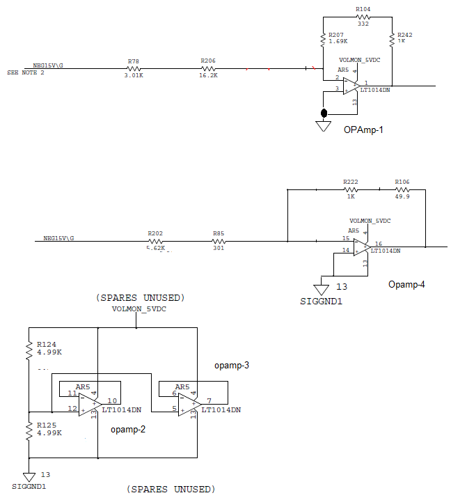
i.e non inverting input voltage is 2.5V and output voltage is 2.5V for op-amp-2 and op-amp-3

Op-amp-2 and op-amp-3 output not connected any circuit


Please find LT1014 circuit connection

  • Rahul,

    I built a similar circuit earlier today. I didn't have any trouble with it.
    Does this problem only happen in simulation?
  • Thanks for inputs


    We observe the problem while testing -40C ambient temperature


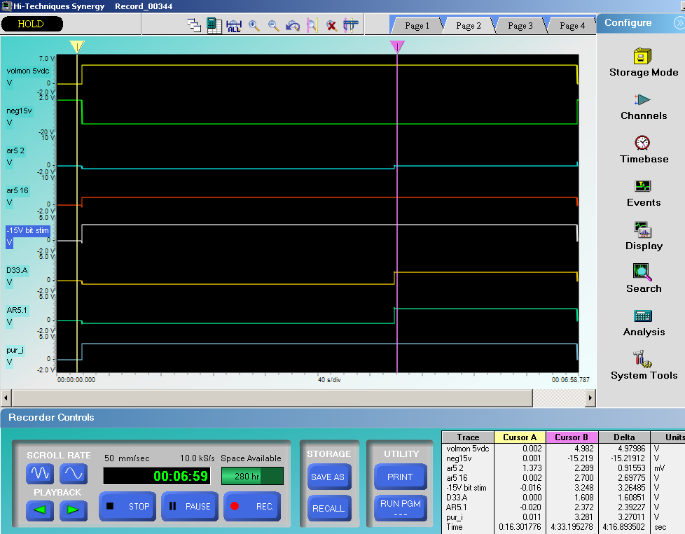
    Test results


    CH1 – AR5.1 w.r.t 13 (power supply of opamp)

    CH2 – NEG15VDC/G (R78.1)

    CH3 – AR5.2(opamp-1----inverting input )

    CH4 – AR5.16(opamp -4 output)

    CH5 – U102.15 (15V stim)

    CH6 – D33.A(inboard signals) others signals

    CH7 – AR5.1(opamp-1----output)

    CH8 – pur_i((inboard signals) final


    Observations:

      1. As AR5.1(opamp-1) output is not functioning for ~4 minutes at -40 deg C, -15V monitoring is failing


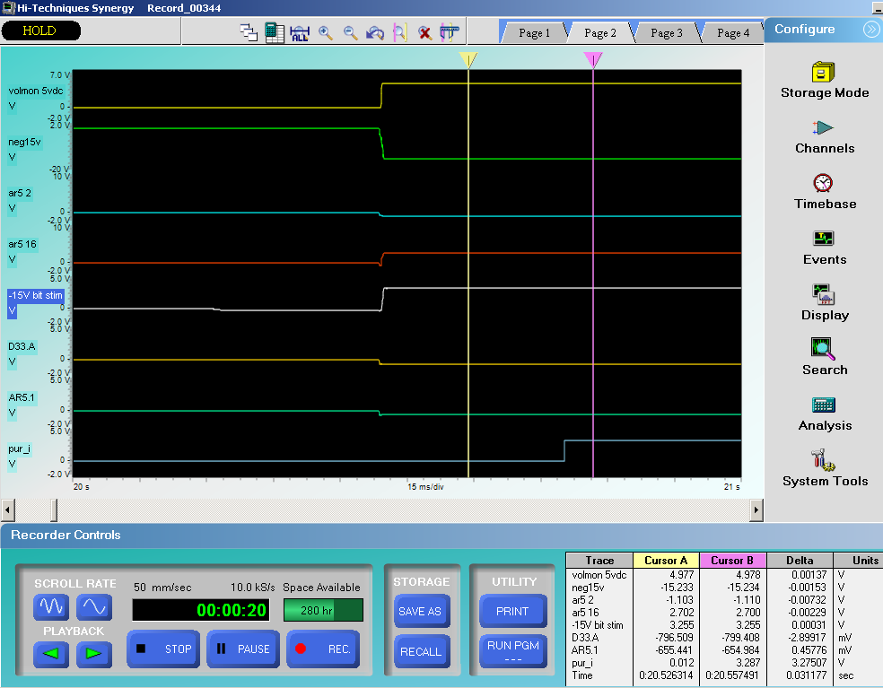
      2. At -40 deg C ambient temperature, AR5.1 output is at – 655mV (driving below gnd voltage) for ~4minutes. During that time, inverting input is also at -1.1033V (it implies it is not in closed loop), refer to below waveform yellow cursor measurements.


      1. After initial delay of ~4 minutes, the AR5.1 output and inverting input voltages were recovered to proper levels, refer to Cursor B measurements.


    Zoomed waveform at power up


    Can you please confirm is our design is with in limits of LT1014D specifications

    Thanks

    Prem

  • I don't see an issue with the usage. On Wednesday, I retest my setup at cold temperature.
  • Hello Ron Michallick

    Thanks for inputs

    Are you test with following condition

    Power supply(5V) of op-amp is rise after -15V voltage applied to input.

    Thanks

    Prem

  • Premchand,

    I tried -40C but was unable to get my parts to malfunction. I tried other input voltages too, but no luck.
    I need to use your results to figure this out.

    Do amplifier channels 1 and 4 recover at the same time? Do the unused channel outputs 2 & 3 go to 2.5V right away?
    I want to know if the whole device has a delayed start up or just one or two channels.

    Maybe it is the negative voltage on inputs or maybe the output being negative that cause the issue.
    If a 5V in series with 1.5k resistance was added added to the outputs would that mask the problem? This should keep the output positive.
    If only one channel had a negative input would that mask the problem?
  • Premchand,

    Is this a new application? Do all devices have a delayed start up?
  • Hello Ron Michallick

    it new application project . only opamp-1  output is delay renaming op-amps giving correct operation

    connected schottky diode to input of  inverting pin of opamp . now problem solved . is it good solution ?

    Thanks

    Prem

  • Prem,

    This should work well.