This thread has been locked.

If you have a related question, please click the "Ask a related question" button in the top right corner. The newly created question will be automatically linked to this question.

OPA548: output latch and triangle output

Part Number: OPA548

Hi team,

Posting for a colleague. We are running into an issue with the output of the OPA548. Sometimes it latches to the positive rail and sometimes the output is a triangle wave which follows the input excitation signal.  

So far we have tried adding a resistor across the input pins to discharged any stored charge and have increased the current limit of the part. Both helped, but don't eliminate the problem completely.

Resetting the device does not solve the latching issue, but shorting the input pins (1 and 2) always corrects the issue (but eventually it latches at a later time).

Has this issue been seen before? Why doesn't a power cycle reset the latch?

Thanks,

Nate

  • Some potential causes of the issue could be:

    1. Charge storage issue: the resistor across the input pins should have addressed this, but it only delayed the issue so it may be something else.

    2. Thermal issue: Do you have a way to conduct thermal imaging or any other thermal tests to see if this affects the part? The part has an internal thermal current limit which may be causing the triangle wave.

    3. Current being forced back into the device: Usually this happens with inductive loads, but you can also add Schottky diodes to the power supply rails and a TVS from the V+ supply line to protect against any transients.

    Best regards,
    Nate
  • Hi Nate,
    To add more clarity to this problem and to answer your questions of thermal and output transients:

    - Parts are heat sunk onto a large piece of Aluminum and can set finger on after a long period of time (once thermal equilibrium is achieved the part temperature is between 50 - 60C. Doesn't explain the latch state that the part goes into?

    - As far as transient causing the part to go into this state.... We have injected high levels of ESD using a ESD gun into the output of the device loaded and unloaded as well as both polarities upto 15kV. No problems.

    - We have tried to create a lot of conditions to try and force this device to go into this latch state and can not do it. We have set inputs to have voltages when no power supply voltage is on ....doesn't cause the issue.

    - Both modifications as you mentioned above (changing to max current limit and to add resistance across inputs help but do not fix the problem on some parts.

    one other note is that the power has to be applied to the device and then inputs pin 1 and 2 need to be shorted to get the part out of the latch mode.
  • Nate,

    I am adding this information to that you previously provided.

    Regards, Thomas
    Precision Amplifiers Applicaitons Engineering

  • Hello Thomas,

    Please see my comments and questions.

    - Parts are heat sunk onto a large piece of Aluminum and can set finger on after a long period of time (once thermal equilibrium is achieved the part temperature is between 50 - 60C. Doesn't explain the latch state that the part goes into?

    The OPA548 junction temperature operating range in normal usage should extend up to 125°C. Datasheet sections 11.3 through 11.5 cover the thermal requirements quite extensively. If the OPA548 die temperature reaches approximately 160 °C, the output current shuts down until the die cools sufficiently. The triangulation of the output waveform is more indicative of the edge rates being limited by reduced output current and not a full shutdown.

    - As far as transient causing the part to go into this state.... We have injected high levels of ESD using a ESD gun into the output of the device loaded and unloaded as well as both polarities upto 15kV. No problems.

    We haven't subjected the OPA548 to in-circuit HV ESD.

    - We have tried to create a lot of conditions to try and force this device to go into this latch state and can not do it. We have set inputs to have voltages when no power supply voltage is on ....doesn't cause the issue.

    Piezoelectric loads present a huge capacitive load at the amplifier output. There may be an inherent stability issue with the circuit design, which is something we are going to assess. Even if the phase margin isn’t sufficient to assure stability that likely isn’t the cause of the output triangulation. A piezoelectric load can produce a significant back EMF if they are subjected to mechanical shock. The lack of output protection diodes in the output circuit as shown on datasheet Figure 38 can result in charges accumulating in the OPA548 die substrate. If that happens, the normal internal circuit operations can be disrupted. It is important to know if adding the diodes corrects the behavior. Note there also needs to be an appropriate transient voltage suppressor connected from the supply pin, to ground, for the protection diodes to do their job.

    Originally the piezoelectric load was described as a 16 nF load. However, there is a TINA schematic showing the capacitance is 36 nF, shunted by a series L, C and R. Which one is the correct load? Also, is the OPA548 output being slammed against one, or both, of the output swing rails? 


    - Both modifications as you mentioned above (changing to max current limit and to add resistance across inputs help but do not fix the problem on some parts.

    There may be a thermal issue at work here.

    -One other note is that the power has to be applied to the device and then inputs pin 1 and 2 need to be shorted to get the part out of the latch mode.

    Originally, there was a mention that momentarily shorting the non-inverting input to V+ temporarily brought about the expected output. Now it appears that shorting the inputs together does that too. There is not enough known about this issue to speculate why that happens.

    I suggest that you request a Failure Analysis be started on some of the devices that exhibit the triangulated output condition. The request is made through the Authorized TI distributor from whom the OPA548 devices were obtained. They will provide you with a Failure Analysis Request form that provides complete instructions.

    Regards, Thomas

    Precision Amplifiers Applications Engineering

  • Hi Thomas,
    Thanks for the response. We have not added any protection on the output of the drivers. We have done extensive transient testing, much worse than the piezo elements can produce and do not see this problem. Have you ever heard/seen this latch up state on these devices during a transient or back emf condition? Have you seen this latch up at all with this device before? In order for us to add these devices on the output would take a lot of effort and may takes weeks of more testing. We have currently 500 drivers and see these latchup at about 10 -20%. Some may never have this issue while others may repeat. Always fixable by shorting pins 1 and 2 together.
    Your question regarding the load:
    The load is around 16nF. I was playing with much larger values to see how the amplifier would handle it during simulation.

    regarding a failure analysis: These parts aren't failed parts. They stop working but can be made to operate again and may never fail again. Not sure a FAE will find anything. Also we sent you 2 parts months ago and nothing ever became of this. This is back when we thought they were damaged.
    Can we please discuss this via a telephone call ? The back and forth via email is taking way to long. We are in the middle of trying to produce over 5000 of these circuits and are getting very worried about meeting our schedule.
    Thanks,
    Tom
  • Any chance of a phone call?
  • Hi Thomas,

    Sure, let's take this off the E2E so we can discuss the issue in depth. However, please allow us to complete the stability analysis of the circuit first before making the call. We hope to have that completed by tomorrow. Then we can then rule that in, or out, as a possible factor.

    To answer your question, we have not seen or had any other reports of this type of behavior with the OPA548. It may be something unique associated with driving the high capacitance piezoelectric load. 

    My number is (520) 750-2169.

    Regards, Thomas

    Precision Amplifier Applications Engineering

  • Thanks, I will call tomorrow later in the day.
    Tom
  • Hello Thomas,

    I have another appointment later in the afternoon. Please try to call me by 2130 UTC (2:30 pm MST).

    Regards, Thomas

    Precision Amplifiers Applications Engineering

  • Hi Thomas,

    Any chance we can meet 1/2 hr later than you suggested. 22:00 UTC, 3:00pm MST, 5:00 EST

    Thanks,

    Tom 

  • Hi Tom,

    Okay, but I will have to leave the call 3:30 MST. I think a half hour should be enough time to cover what what needs to be discussed.

    Regards, Thomas
    Precision Amplifiers Applications Engineering
  • Okay, sounds good!
    Thanks,
    Tom
  • Hello!Now I have a weird question about the OPA548, the OPA548 is used for a follower in my circuit. In my circuit,the OPA548 will provide 2A current for the load resistance.But,when the ammeter is connected to the circuit that can provide negative current of 2A(Notice: the load is empty this moment ). At the same time ,I discover the output waveform of OPA548 is sine wave.And the OP-amp oscillation. Can you can me?
  • Hi Yang,

    It sounds like it may be a stability issue. My recommendation is to post this in a new thread here since this is a separate question. Can you also do a load step test and see what the overshoot is? (use a small signal step, not full scale).

    Thanks,

    Nate

  • Thank you for your answer!

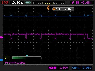
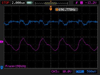
    • Now,I describe my circuit. In the circuit that the power of OPA548  is ±30 voltage , And when the load is 1Ohm  the OPA548 output  5 voltage .First,When the OPA548 output  positive 2 Amp(And the load is 1Ohm),the output waveform is like the picture 1. (Notice : my input signal is   DC signal all the time ) In the picture , the waveform should be straight line ,because of the input signal is DC .But the  wave is square wave.(I think that is very ***)    Second, when the OPA548 output negative 2 Amp ,the output waveform is  picture 2. the wave of the picture 2 is oscillation ?  I  add that when the OPA548 output  either positive 2 Amp or negative 2  Amp ,the first  3  seconds is fine sometimes .There are two ideals that the first is stability and the second is overheating protection. For stability , I add the RC snubber  at the  exit of OPA548 ,but the way is useless. But  I think  overheating protection is more possibility . So far my problem is still unresolved.Can you help me??   What happened ?        

                               picture 1

        picture  2  

  • Hi Yang,

    Thank you for the quick reply. Please post this information in a new thread so that we can properly track and close your question. When new questions are added to existing threads tracking becomes difficult if there is already a suggested answer.

    Best regards,

    Nate