This thread has been locked.

If you have a related question, please click the "Ask a related question" button in the top right corner. The newly created question will be automatically linked to this question.

TLV1702: elementary opamp question

Part Number: TLV1702
Other Parts Discussed in Thread: LM311, LM311-N, , TLV1701, LM339

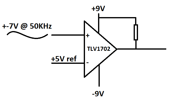
I have a circuit like in the attachment. What I need is to get only positive voltage at the output. What are my options? Using a serial diode at the output at this frequency distorts the pulse shape of the output signal, using a parallel diode to the load does not give a perfect zero based signal, changing -9V supply to 0V(gnd) is not allowed as far as I know if there is negative signal at the input (or am I false?) So what can I do? Thanks.

  • Hello Mustafa,

    You could add a transistor to the output to level shift.

    Is supply current an issue? Instead, you could use the LM311 or LM311-N, which is specifically designed to have the "comparator" portion run off a split supply while the output is a "floating" open collector output (with a separate "ground" for the output). This would give you your desired GND to Vlogic signal.

    V+ and V- would be +7V and -7V respectively, GND would be GND. It will need a pull-up resistor on the output to Vlogic (just like the 1702). The output will then swing between GND and Vlogic.

    If not using the strobe or balance, connect pins 5 and 6 together. To make it go even faster, tie pins 5, 6, and 8 together.
  • How can I use transistor? Applying -9V to the base will damage the transistor, right? I'll think lm311 for the next prototype but currently I need a solution for tlv1702.

  • Also I'll go upto 350 or 400KHz. Are there any comparators suitable for this? Thanks.

  • Hi Mustafa,

    See attached TINA sim for the simple output circuit. The series 10K resistor limits the current and the diode clamps the negative voltage.

    /cfs-file/__key/communityserver-discussions-components-files/14/4331.level_2D00_shiftt.TSC

    The TLV1701 is a micropower device, which is slower than "normal" power devices.

    400kHz is the "toggle rate". From this we need to find the maximum prop delay required.

    The "toggle rate" of a comparator is generally considered the combination of the risetime, falltime, positive prop delay and negative prop delay.

     Ftoggle = 1/( tr + tf + tplh + tphl)

    But we need to know roughly what value prop delay we need for 400kHz. So we will ignore the rise/fall time for now.

    t_toggle = 1/400kHz = 2.5us

    Since there are two transitions within that time, we need a comparator to half that value.

    tprop = 2.5us/2 = 1.25us (let's say 1us)

    You need to find a comparator with a maximum prop delay of 1us.

    There are many comparators that would work. Because of the 18V supplies, most of them are open collector output (LM339 series).

    But your best choice is still the LM311, which has a 115ns prop delay and does not need any level shifting on the output, which would eat into the bandwidth.