This thread has been locked.

If you have a related question, please click the "Ask a related question" button in the top right corner. The newly created question will be automatically linked to this question.

OPA541: Paralleled Operation for the OPA541

Part Number: OPA541
Other Parts Discussed in Thread: OPA549, TINA-TI

Hello,

I have a small question about the use of the OPA541 in "Paralleled Operation" mode.
In the datasheet, it's specified that this assembly works as an inverter, but does it works in non-inverter mode?
When I did the test, my power supply is short-circuited and the second OPA541 (slave) heats up enormously and very quickly.
On the other hand, when I test with a single OPA541 (the master), it seems to work.
I could send you the design if you wish.

Thank you in advance.

Florian

  • Hi Florian,

    It appears that the two OPA541 parallel op amp configuration driving the non-inverting input can be realized. I ran a quick simulation on the databook circuit modified such that the non-inverting input was being driven. The simulations looked good for both a large-signal sine wave drive, and a small-signal transient analysis.

    It is possible that the circuit might be breaking into oscillation once power is applied. If one, or both, of the amplifiers oscillate at a high frequency a condition can occur where both output transistors get turned on at the same time. If that happens current can shoot through directly from one supply (+Vs), to the other (-Vs), and the current through the OPA541 be very high. Any OPA541 in which this occurs will dissipate a lot of heat and can even be damaged. If you can provide power supply current limiting it might help save an OPA541 in the test from destruction.

    Please do provide your schematic, power supply info, input signal info, and the load you have connected to the output.

    Regards, Thomas

    Precision Amplifiers Applications Engineering

  • Hi Thomas, 

    And thank you for your answer and informations.

    Please find my schematic. For the others informations :

    - Power supply : ±39,5V (2 differents power supplies)

    - Input signal : ±4V sine signal ; it's a signal with 4 sines of 1200Hz frequency, but I don't know the period. I can search it if you want.

    - The load : It's a coil of 1,9H with a resistance of 11Ω which we can add the cable resistance, at the maximum 40Ω.

    Regards, FlorianSchéma simulation.pdf

  • There's a mistake because on my schematic, power supply is ±40V, but in reality, it's ±39,5V.
  • Our old design works with one OPA549 non inverting, and it works very well. We want to double current and voltage, that's why we change of parts and double it.

    Regards, Florian.
  • Hi Florian,

    I have been analyzing your parallel output OPA541 op amp circuit. I did a preliminary stability analysis with a 11 Ohm output load and the circuit appeared to have plenty of phase margin. So for that partiulcar resistive load case the circuit appears to be stable. However, once the output goes from being purely resistive and begins to incorporate reactance a stability issue can be created.

    Just so we can either rule in, or rule out, a stability issue I need to know a bit more about your load. You mention a coil with 1.9 H and 11 Ohms, and a cable resistance of 40 Ohms. Is the cable a shielded cable, twisted pair, or something else? Does it have part number? How long is it? I am trying to determine if it is appearing as a significant capacitance across the inductor.

    A concern too is the supply voltage you are using with the OPA541 amplifiers. Initially, you mentioned supplies of +/-40 V but revised that to +/-39.5 V. Either case represents a level that is at, or very near, the absolute maximum rating. Commonly, the OPA541 uses +/-35 V, or less supply levels. I am wondering if your supplies really are very close to +/-40 V if the device is going into HV breakdown. Using such high voltages creates the possibility that if the supply overshoots breakdown might occur. Would it be possible to try using a supply level such as +/-35 V and see if you still have the issue you mentioned?

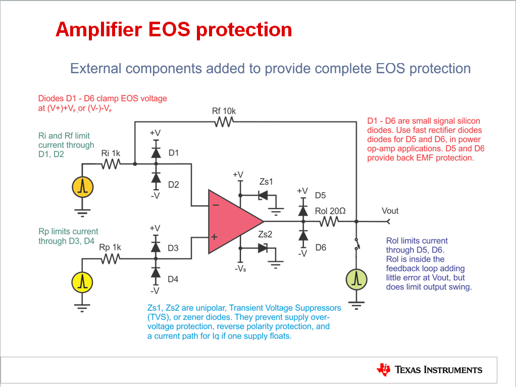
    Also, you mention the power supply is different supplies. Are the two supplies turned on simultaneously? If one supply comes up before the other a latch condition might be created. Should that happen very high current can flow through the amplifier, through unexpected internal paths. We always recommend having a transient voltage suppressor (TVS), or zener diode, of appropriate sustaining voltage be connected from each supply pin to ground This is especially true for power op amp applications. That way if one supply comes up first, the TVS truns on provies a path for return current until the other supply comes on. Then the TVS turns off. You can see the TVS diodes in the image shown below. They are labeled ZS1 and ZS2.

    Regards, Thomas

    Precision Amplifiers Applications Engineering

  • Hi Thomas,

    Concerning the cable :
    - It's a shielded cable, twisted pair of 2,5mm².
    - His lenght is from few meters to 120m maximum. It's not always the same lenght.

    I will test today with power supply such as +/-35 V.

    The two supplies are turned on simultaneously, but I can add TVS on my design.
    I don't know all its properties, but what is sustaining voltage?Maximum reverse standoff voltage?Breakdown voltage?Clamping voltage?
    Its value must be my power supply voltage, that's it?

    Regards, Florian
  • Id did an another test (if it can help you):

    - I did a test with only one OPA541 (like I said before), and it works.
    - I did this test with the second OPA541, but only powered on, there was nothing on pin 1, 2, 5, 7 and 8. There wasn't problem with power supply, the two OPA541 were correctly powered on. It's when I plugged pin 5,7 (the output) that nothing works.

    Regards, Florian
  • Reducing the power supply to +/-35V, the power supply is not over short-circuited, but the second OPA541 still heats up a lot.
    Does this come from the fact that it may be HS following an overvoltage?
  • I have an another question ; do you know an another amplifier, which I can powered on with +/-40V, has approximately the same characteristics as the OPA541 (output current, ...). Because I want on the output a signal with high current, and a voltage of approximately +/-39V.
    However if it's not possible, I will keep the OPA541 and reduce the output voltage.

    Thanks for your answer.
  • Hello Florian,

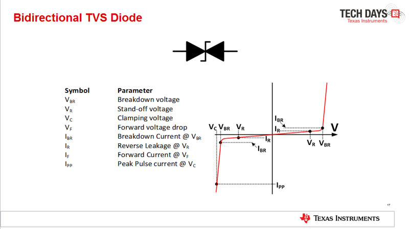
    The TVS diodes will need to have a reverse standoff voltage (VR) (VSO) approximately equal to the supply voltage you plan to use with the circuit. If the supply is set to 35 V, then use a diode with a Vso of 35 V. The breakdown voltage (VBR) will be a few volts higher and that is where the onset of voltage clamping starts. You can see these voltage points indicated in the slide image:

    An example of a Littelfuse 36 V TVS is the SMAJ36A. Its electrical information can be found here:

    Another issue I found with your circuit is the absence of output protection back EMF diodes, as seen in OPA541 datasheet Figure 13. "Clamping Output for EMF-Generating Loads." The highly inductive load connected to the output can produce a high-voltage back EMF that disrupts the normal operating conditions of an output transistor that can even result in damage to the output devices. The diodes, connected as shown in Figure 13, should always be included when driving inductive loads.

    The 1N4003 diodes shown in Figure 13 are likely a little light for the application. I would use a higher current, fast rectifier diode such as the ES3BB for D1 and D2. Here is where you can view the datasheet for the ES3BB diode:

    The fact that the cable can be different lengths can make compensation difficult because the capacitance presented across the load inductor and the opamp output will be proportional to the length. Compensation established one particular load condition may not be effective for another.

    Regards, Thomas

    Precision Amplifiers Applications Engineering


  • Florian,

    I suggest you connect oscilloscope probes to each supply and to each OPA541 output. Look for anything unexpected in the waveforms when you apply the supply voltage. Be sure the supplies are coming up at the same time.

    Regards, Thomas
    Precision Amplifiers Applications Engineering
  • Florian,

    The OPA541 is our highest voltage power op amp, rated with the absolute maximum supply ratings of +/-40 V. All of the other high current, high voltage, power op amps are rated with lower supply voltages.

    Regards, Thomas
  • Hi Thomas,

    Thanks for your answers. So my final design will be like that?

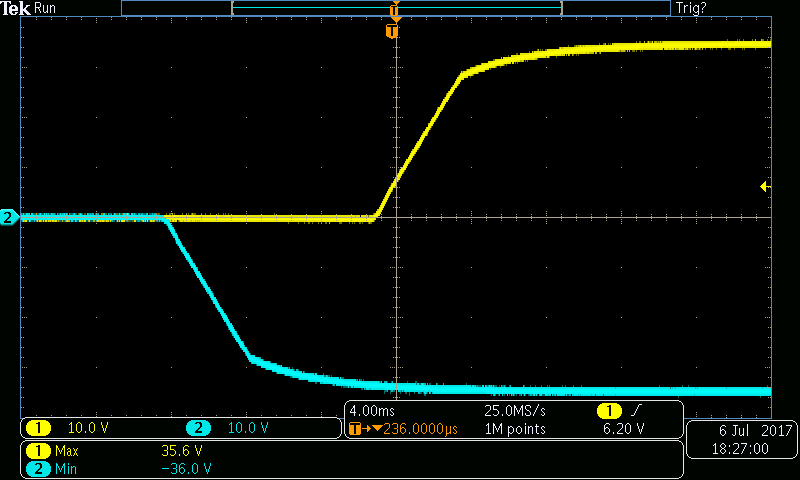
    I attach too supply's waveform ; we can see that V- comes before V+ (about 12ms).

    For the moment, I don't know if the system works because I haven't got no load on the output. 

    The second OPA541 (which I changed) heats up more slowly than before.

    Regards, Florian

  • Hi Florian,

    Thanks for the images of the power supply start-up sequence. A 12 ms delay between them could prove significant in the case of the one device drawing high current. Having the TVS diodes connected from the supply pins to ground will provide a current return path until the other supply comes up. Hopefully that will help.

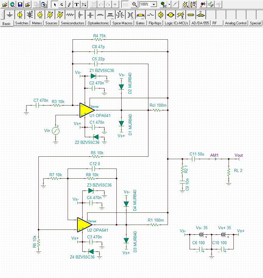
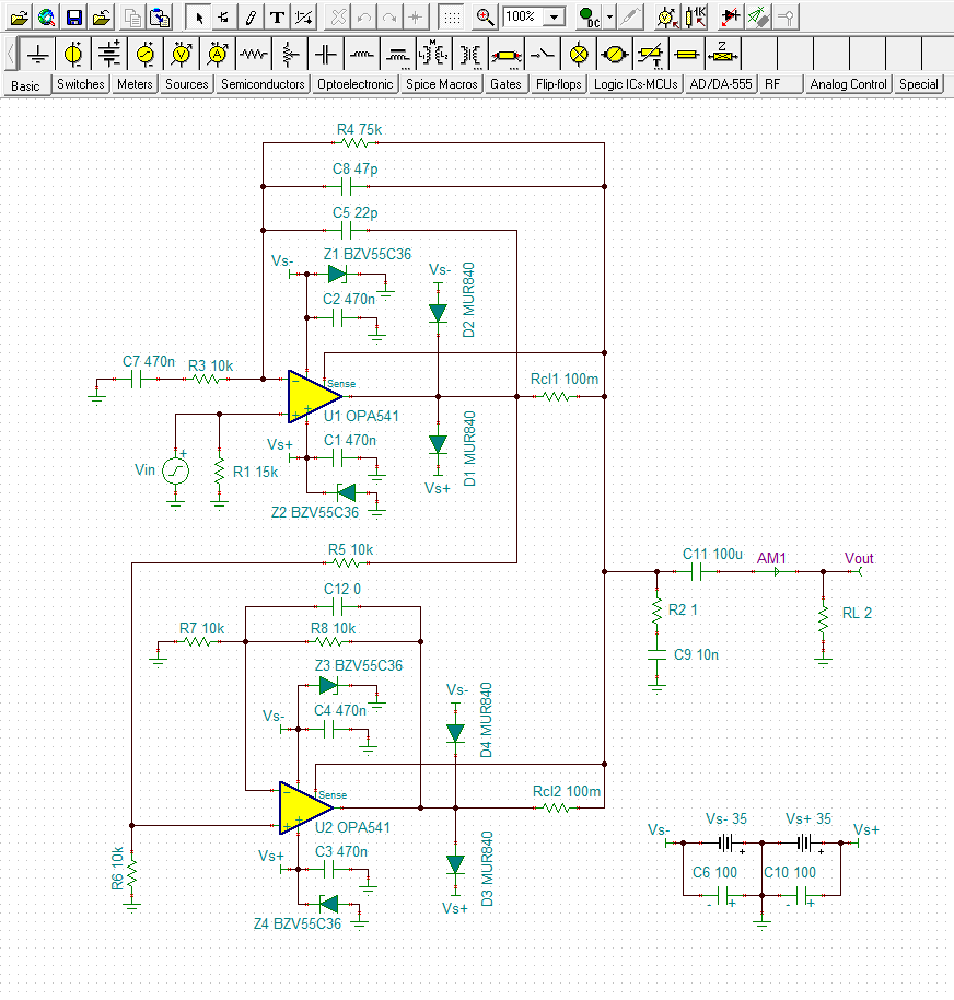
    I was discussing the circuit problem you were observing with one of my colleagues and he acknowledged that getting two, or more power op amps working in parallel can pose some unexpected challenges. He had some issues with the way the OPA541, Figure 15, configured the two parallel op amps. He was concerned that there might be a common-mode voltage violation upon start-up and that may be setting up one of the op amps for the high current condition. He suggested that the circuit associated with the second amplifier be converted to a difference amplifier configration. That eliminates the possibility of the second op amp having a common-mode violation. I have illustrated this change in the TINA diagram shown below.

    The diagram also shows how the output protection diodes and the TVS diodes are to be connected. I didn't have models for the devices I recommended in my previous post so I used some convenient devices to show their positions. Note that I have moved a couple of other components around as well. Also, I am not sure if the compensation from the previous circuit holds for this arrangement and that may have to be further evaluated.

    Regards, Thomas

    Precision Amplifiers Applications Engineering

  • Hi Thomas,

    Questions about your diagram :

    • Where is the pull-down resistor (R1 on my diagram)? If we haven't signal on Vin, it's important, no? She is on U2 (R6, 10k), but not on U1.
    • U2 is now a non-inverting amplifier with a gain of 2 (Vout=Vin*(1+R8/R7)), why? What is the global gain of my diagram?

    Thanks.

    Regards, Florian

  • Hello Florian,

    • Where is the pull-down resistor (R1 on my diagram)? If we haven't signal on Vin, it's important, no? She is on U2 (R6, 10k), but not on U1. - I have added R1 to the diagram. Do note that if the siganl source impedance is low and provides a return current path, R1 is not required.
    • U2 is now a non-inverting amplifier with a gain of 2 (Vout=Vin*(1+R8/R7)), why? What is the global gain of my diagram? - The mid-band gain of U1 is as you have indicted by the equation would be +8.5 V/V. U2 operates with a non-inverting gain of 2 V/V, but it is preceded by the gain of 1/2 V/V divider comprised of R5 and R6 shown in the diagram below. The overall gain through that path is (2 V/V)(1/2 V/V), or 1 V/V. The U2 circuit simply amplifies the U1 output by 1 V/V. Thus, both U1 and U2 have the same output voltage swing as is required for parallel operation.

    Regards, Thomas

    Precision Amplifiers Applications Engineering


  • Hello Thomas,

    Sorry for the delay, I wasn't at my office.

    In Tina, I don't find this model of OPA541, with the Sense pin. Where can I find it?
    I will test the new diagram this afternoon, I will keep you informed.

    Regards, Florian

  • Hello Thomas,

    I do the test with the new diagram ; I saw many things :

    • On the output, I have my amplified voltage, so it works.
    • The second amplifier doesn't heat up, but the first yes. I did the test without the protection diodes, can the problem comes from here?
    • I will continue my tests, to see if the current is well doubled.

    Regards, Florian

  • Hello Florian,

    I have attached my TINA circuit so that you can access the OPA541 simulation model that provides the sense function. This is a much newer version of the model than the one that is available within TINA-TI macros, or product web page.

    If you wish to build a new circuit you should be able to copy and paste the OPA541 from the attached TINA circuit file.

    Regards, Thomas

    Precision Amplifiers Applications Engineering

    OPA541_noninv_parallel_04.TSC

  • Hello Florian,

    Do you know for sure that each OPA541 is providing half the total output current? If so, then make sure each OPA541 has the equivalent thermal environment.

    Can you provide the schematic that you have settled upon using the two OPA541 amplifiers in parallel?

    Regards, Thomas

    Precision Amplifiers Applications Engineering

  • Hello Thomas,

    And thanks for your answer.

    Firstly, I said you a mistake : the voltage of my input signal is +/- 8,5V.
    I changed my power supply to have +/-37,5V.

    I joined you the schematic that I settled (without diodes, I receive it today).

    I will measure today that each OPA541 provides the half of the total output current.

    If it's not the case, where does the problem comes from?

    Regards, Florian

    Essais_simul - 3.TSC

  • I said another mistake, I wrote to quickly. My input signal is +/- 4,5V. Sorry.

    I will reduce a little the gain of my amplifier because 9V peak to peak * 8,5 = 76,5V so it's too high, cause my circuit is powered-on with +/-37,5V.

    When I simulate with "Transient", I have this error message : "Convergence problem. Check the analysis parameters!"
    I don't know Tina very well, so I don't kwow where's the problem comes from. And my curves look so bad.

    The unit of AM1 is A?

    Thanks.

    Regards, Florian
  • One another thing i saw ; the first OPA541 heats-up when I increase my input signal :

    - When the input signal is low, it doesn't heats up

    - When I increase the amplitude, it starts to heats up.

    PS : I sent you the new schematic, with the input signal uploaded (Vin = +/-4,5V)

    Regards

    0564.Essais_simul - 3.TSC

    6242.0564.Essais_simul - 3.TSC

  • Hi Florian,

    If you can't place ammeters directly in series with each OPA541 output, you should be able to measure the voltage drop across each 100 milliohm sense resistor. Having the voltage drop and the resistor value will allow you to calculate the output current for each output. Since you are driving the circuit with an ac signal a DVM with RMS measurment capability would be best. The resulting output currents should be close if the circuit is operating correctly.

    Do be sure to monitor the output volatge across the load with a DSO. Make sure the signal is clean and free of any oscillation, or unexpected signal behavior.

    Regards, Thomas

    Precision Amplifiers Applications Engineering

  • Hi Florian,

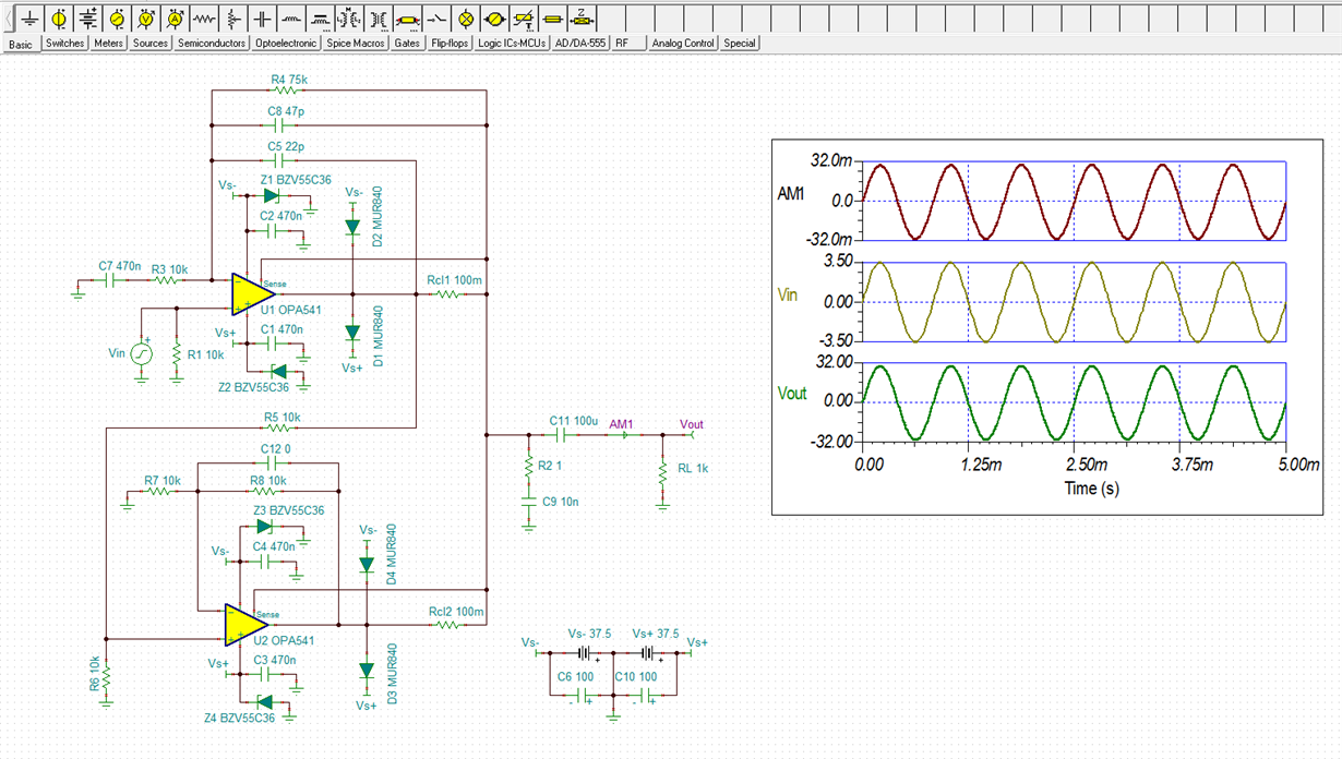
    I have noted your changes and have modified my OPA541 TINA circuit accordingly. It uses the latest OPA541 TINA model. I have attached that file so that you can simulate the circuit. Note that you had specified a 1-kohm load in your circuit and I have added this to mine. You may wnat to increase the load on the OPA541 output.

    You can see an example of a simulation results below. I haven't had any convergence issues when doing the various simulations.

    AM1 is an ammeter.

    Regards, Thomas

    OPA541_noninv_parallel_05.TSC

  • Hi Thomas,

    I will measure today the voltage on the 2 100 milliohm resistors to see the current on each.

    I used your file to simulate the circuit. When I want to change the input signal (3,5V ==> 4,5V), and I do "Analysis", "Transient", I have this message :

    Where does it comes from?

    Because when I test in real, my output signal is correct.

    Regards, Florian

  • I did 2 omeasures with an ammeters, with an input signal of 4V peak to peak :

    - Voltage on Rcl1 : 10,6mVac
    - Voltage on Rcl2 : 11,9mVac

    After, I try to plug the oscilloscope on Rcl1 to see the voltage ; my 2 power supplies were short-circuited. Does this come from the fact that U1 may be HS following, given that it heated up a lot before?

    Regards, Florian

  • Hi Florian,

    I expect that there will be a small difference in the current that each OPA541 contributes to the total output. Some of that comes from the resistor tolerances; especially R5 though R8, and the two output current limit resistors Rcl1 and Rcl2 in my TINA schematic. Resistors R5 through R8 should be low tolerance, 1 % or better, preferably 0.1 %. Because of U1 and U2 operate with different loop gains U2 will provide a little less current than U1. That can be compensated for by reducing R5 from 10 k-ohm, to about 9.98 k-ohm.

    I didn't suggest measuring the voltage across Rcl1 and Rcl2 with a O-scope because I was concerned that the ground return lead might be connected to the ac line's ground. Such measurments are best accommodated by instruments that do not have an input hard wired to the ac ground. This may have been the issue that caused the power supply short. When you disconnected the O-scope did the short the short cease?

    Regards, Thomas

    Precision Amplifiers Applications Engineering

  • Hi Florian,

    When you increase the input voltae to 4.5 Vpk with a U1 gain of +8.5 V/V, the output with the 1 k-ohm load is going to try and swing +/-38.25 V. That level is 0.75 V beyond the power supply setting of +/-37.5 V. Apparently, that is causing problems for the simulator's math engine and convergence cannot be attained.

    Reduce the input level so that the output remains within its linear operating range, or add a much heavier output load so that the output cannot swing beyond the power supply rails. When I drive a 2-ohm load for a total output current of about ~13 Amps, the output swing is limited to about +/-26.5 V, which is well below the +/-37.5 V supplies. That circuit condition converges without any problems.

    Regards, Thomas

    Precision Amplifiers Applications Engineering

  • Hi Thomas,

    When I disconnected the oscilloscope, the short was also here. I changed the first OPA541 (U1, where I plug the oscilloscope), the problem was solved.

    The thing I don't understand is why the first OPA541 heats up when I increase the input signal? The second is cold, however, they have approximately the same output current...

  • Thomas,

    I'm agree with you with the input signal of 4,5 Vpk and the gain of 8,5V, which are higher than the power supply.
    But I reduced R4 at 72kOhm to have a gain of 8,2 ; so my level is +/-36.9V, so in real, it should be work. But in simulation, he doesn't ("Convergence problem....)

    So I try with a gain of 8 (R4 = 70kOhm), but as show in the attached file, my Vout signal is saturated on lower voltage. Why is it like that in simulation? Cause in real I don't think I have this problem.

    Regards, Florian

  • Hi Florian,

    Pspice, or "portable" Spice has its limits in term of the circuit complexity it can support and successfully convergence. Pspice based simulation models are simplified circuits compared to the complex, extensive circuits inside the actual operational amplifiers. Therefore, when we built the OPA541 model some compromises were made to provide resonable representations of the amplifier's electrical behaviors and still be able to converge. Also, parameters such as voltage offset are fixed at a particular value within its specified range, but will likley be different than what you find for the actual device you have on hand. Some differences between the actual device results and the simulated results are to be expected.

    In your simulation the output is swinging very close to the supply rails. It is normal op amp output behavior for the output to clip under that condition. The Electrical Characteristics table provides measues of how close the output can swing to the rails under specific load conditions.

    Regards, Thomas

    Precision Amplifiers Applications Engineering

  • Hi Florian,

    When you increase the input drive to the amplifier circuit the voltage across the output load increases as does the output current throught the OPA541 and the load. It is then a matter of the power that has to be being dissipated and the thermal environmen as to how much the OPA541 heats.

    Why you are seeing a temperature difference between the two, parallel OPA541 is not something that I can determine from this location. If the current is about equal for each OPA541, and each sees a nearly equivalent thermal environment, then the heating should be about the same.

    Regards, Thomas

    Precision Amplifiers Applications Engineering