This thread has been locked.

If you have a related question, please click the "Ask a related question" button in the top right corner. The newly created question will be automatically linked to this question.

OPA552: OP Amp Power Dissipation Question

Part Number: OPA552
Other Parts Discussed in Thread: OPA551

  • Looks like the picture did not take... here is the same thing, but in a PPTX file format.

    OPA552 Power Dissipation 11'17.pptx

  • Hi Mark,

    This is an interesting subject that I don't think any of us have looked into before. Would it be possible for you to provide a schematic of the proposed OPA552 circuit, and the equivalent load impedance of the resolver? That would provide us an example to test any solutions we come upon.

    Regards, Thomas
    Precision Amplifiers Applications Engineering
  • Hi Mark,

    I am having to learn more about resolvers to support your inquiry!

    What I do find when I review resolver electrical specifications is that as suspected, they don't present a purely inductive load to the driver. For example, I am seeing impedances such as Z = 120 +/-j24 Ohms, or 75 +/-j15 Ohms, etc, for small resolvers. Therefore, the majority of the impedance is resistive and the remainder is either inductive, or capacitive reactance dependent on the resolver operating conditions. Certainly the voltage/current phase relationship will be that associated with the particular complex impedance condition at the moment, but it doesn't appear that it will ever be completely inductive.

    Do you have the specifications for the particular resolver you intend to employ in the OPA552 bridged-T driver circuit? If we have the specifications we should be able to get a better idea of the voltage/current phase relationships and what the power dissipation of the amplifiers will be at a particular instant.

    Regards, Thomas
    Precision Amplifiers Applications Engineering
  • Thomas,
    It is true that the resolver is not completely inductive. I am not 100% certain if this is the resolver we have but it would be close:
    www.ltn-servotechnik.com/.../RE_08_EN_01.pdf
  • Hi Mark,

    In the simple schematic you sent to me it showned two op amps in a bridge circuit. Both op amps, although configured as inverting amplifiers, did not have input and feedback resistors. Certianly, that wouldn't be a usable configuration. Also, the OPA552 that you have mentioned is not unity gain stable; it is intended for gains of 5 V/V and greater. Therefore, the OPA551 may be a better choice for gains less than 5V/V because it is unity gain stable.

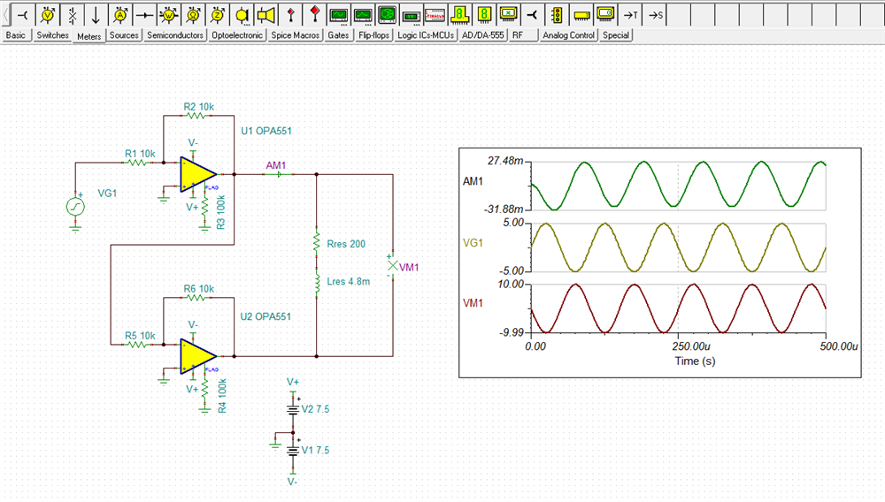
    I propose starting with a circuit such as shown below. It can be modified as needed to meet the application requirements.What do you think?

    Regards, Thomas

    Precision Amplifiers Applications Engineering

  • The circuit above looks good – there is a phase shift between the voltage and the current so the original question is applicable.
  • Hello Mark,

    Regarding your original question:

    A series connected RL load will result in the voltage and current splitting in phase where the voltage leads the current. The output transistors providing the output power will expereince this phase difference as well making the internal power dissipation different than if the amplifier were driving a purley resistive load. Determining the power dissipation for this latter case is much more direct than the complex RL load impedance case.

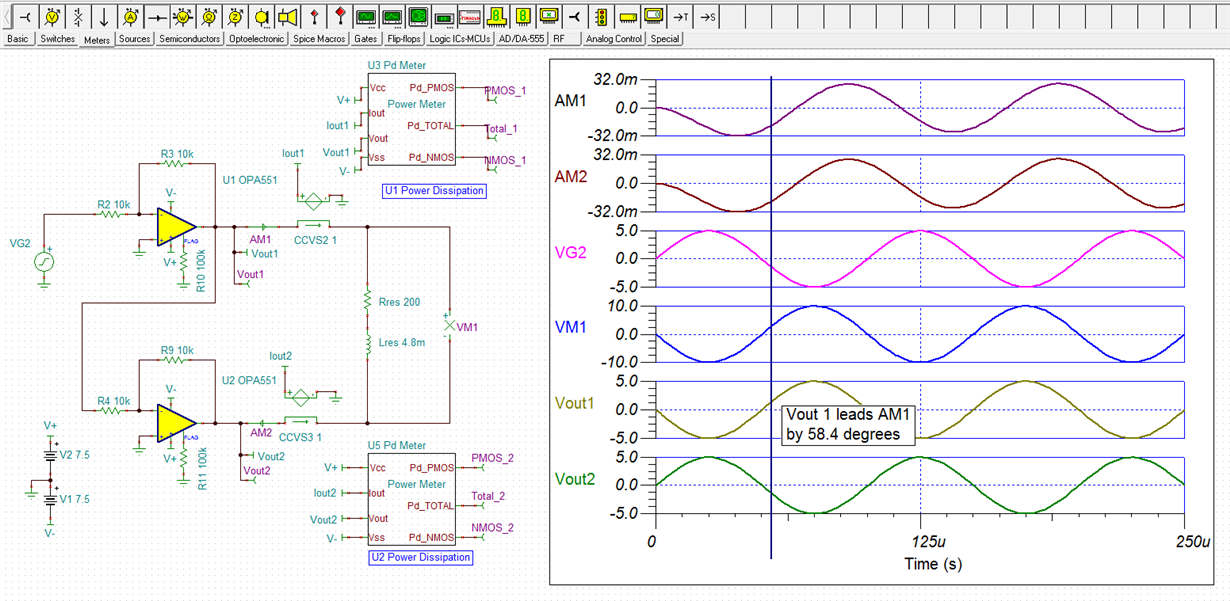
    The OPA551 bridged-T output circuit was analyzed with the proposed resolver load impedance. Special power meters developed by Tim Green were added into the circuit and provide an means of accurately determining the power being dissipated in the output transistors. The OPA551 TINA circuit having the power meters is shown below.

    An initial look at the U1 OPA551 output voltage and current shows that the voltage leads the current by 58.4 degrees. Noting where the blue vertical line crosses the Vout1 and AM1 traces, it can be seen that the output voltage is positive while the output current is in the reverse direction due to the phase split. Power dissipated by the individual output transistors is the product of the instantaneous voltage across each transistor and instantaneous current through each transistor. The upper output transistor can only source current and the lower transistor can only sink current regardless the voltage/current phase relationship of the output load. The power meters can provide insight into the instantaneous dissipation levels. 

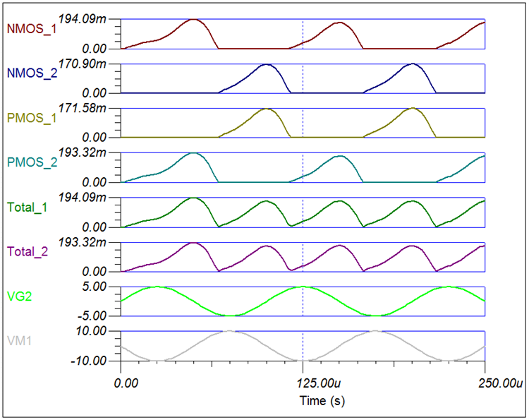
    The next simulation provides the instantaneous power dissipation in each transistor, for each OPA551 in the bridged-T circuit. The OPA551 has a bipolar output, but the power meters are labled for a CMOS transistors. Therefore, NMOS_1 is lower output transistor, and PMOS_1 is the upper output transistor for U1. Likewise, NMOS_2 and PMOS_2 for U2, the second OPA551. Total_01 and Total_02 represent the total dissipation for each OPA551 device U1 and U2. The peak power dissipation is about 0.194 W for each OPA551, when 10 Vp-p is being developed across the load. The Total_01 and Total_02 waveforms would have to be intergrated to determine the average power dissipation.

    I have attached the OPA551 TINA file that includes the power meters. This will allow you to change the load impedance and observe how the transistor dissipations are affected.

    Regards, Thomas

    Precision Amplifiers Applications Engineering

    OPA551_Resolver_03.TSC