This thread has been locked.

If you have a related question, please click the "Ask a related question" button in the top right corner. The newly created question will be automatically linked to this question.

OPA564: Overcurrent flag issues

Part Number: OPA564
Other Parts Discussed in Thread: TINA-TI

I am breadboarding a prototype which is in great hurry, and I am using two OPA564 devices.

I'm trying to achieve a PLC differential output on top of a 24V power line.

I have an input signal square wave of 100-200 kHz with 3.3V amplitude.

One of the OPA564 is configured as a buffer (for the +24V side) and is working great! 

The other device is configured as a simple inverterand I cannot get this one to work at all. 

I am seeing pulses on the OC flag but it is mostly high. even if I don't have anything connected to the output, or input.

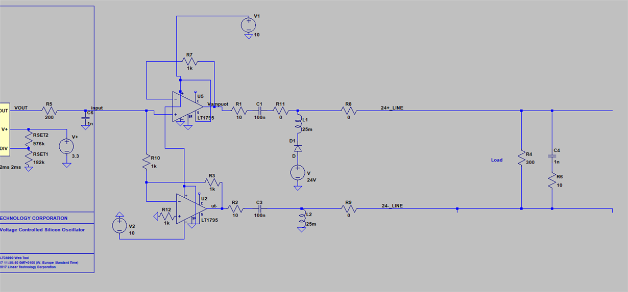
I've hooked it up as my LTspice simulation (ignore the strange parts and really poor job in making a readable schematic, sorry!)

but with a single 10V supply. (and haven't connected any output to it yet because I couldn't get it working)

  • Hello Peter,

    I recreated your OPA564 PLC driver circuit schematic in our TINA-TI Pspice simulator. I included the rest of the components necessary for a functional OPA564. It functioned as it should. You can see the results below.

    The results indicate that the average output current is only about 8 mA so the OPA564 shouldn't be going into current limit. If the load placed across VM1 and VM2 is increased, then the current increases.

    I am not finding anything obvious that would keep the second OPA564 from operating correctly in the circuit. Did you make sure you set the OPA564 current limits correctly in your circuit? Is the underside PowerPad soldered to V- (-10 V)? Make sure the second OPA564 is properly soldered into the circuit.

    Regards, Thomas

    Precision Amplifiers Applications Engineering

  • Thanks for your help! I tried re-soldering the part again, ensuring that the power pad is soldered to the other GND pins. (Just as I did on the high-side OPA which is working). I also added a pull-down resistor on the OC flag (which I don't see any information about in the datasheet? or am I just blind?).

    I am getting the same issue. I haven't connected anything to the inputs or outputs, and have used the voltage-divider approach to go from 9V to 4.5V on Vdig.

    The OPA is now soldered separately with just the neccessary resistors for all the current settings etc.

    As soon as it powers up the over current flag is high.


    Should I order some new parts and consider the two parts I am trying with to be broken?

    Is there any other case where the overcurrent flag would be set other than high output current?
  • Update:

    I connected the new OPA in the same manner as the upper one that works, with 1k feedback resistance and the input signal to Vin+.

    It worked, gave a proper output and the OC flag was 0.

    When I then switch the Vin+ to GND and put the signal in Vin- instead, as per the schematic, the overcurrent is set.


    Can there be some sort of inrush current happening?
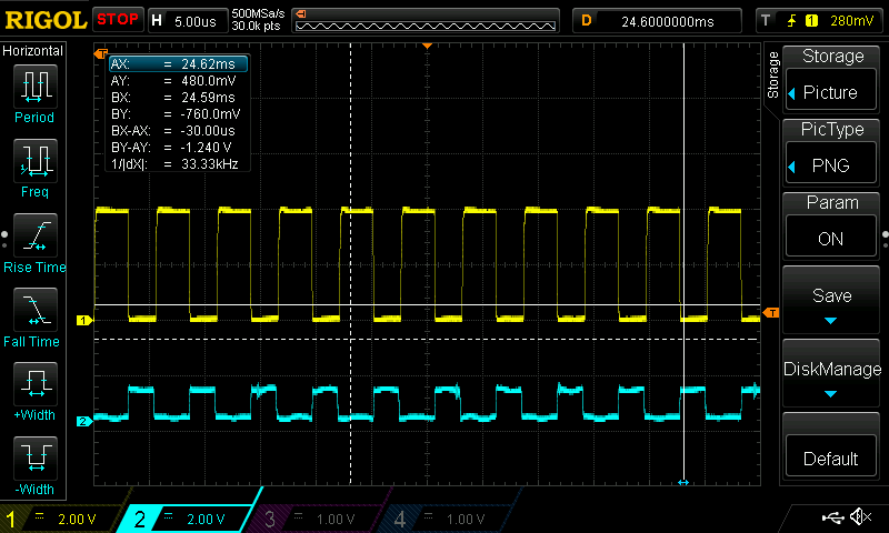
  • I tried adding a capacitor between the 1k resistor and the input signal, which made the output actually work somewhat.

    But the overcurrent flag is following the output, as the image shows.

    (Yellow is OC, blue is output).

  • Hi Peter,

     "I also added a pull-down resistor on the OC flag (which I don't see any information about in the datasheet? or am I just blind?)."

    The current limit flag produces a digital output referenced to V-. The datasheet Electrical Characteristics table indicates:

    The datasheet states on page 21:

    "The output signal of IFLAG is compatible with standard CMOS logic and is referenced to the negative supply pin (V–). A voltage level of + 0.8V or less with respect to V– indicates that the amplifier is operating within the limits set by the user. A voltage level of +2.0V or greater with respect to V– indicates that the OPA564 is operating above (exceeds) the current limit set by the user."

    The current limit flag level should be monitored relative to V-, or in the case of your circuit the -10 V line. The flag pin can't source, or sink, much current so it it should be followed by a high impedance measurement circuit. I suspect if the limitations of the pin aren't observed it could provide an unexpected response.

    Regards, Thomas

    Precision Amplifiers Applications Engineering

  • Hi Peter,

    The OPA564 current limit flag should only activate when the output current exceeds that set ILim. If there is a momentary inrush current flowing to the load that exceeds the ILim, then the ILim flag should only activate during the duration of the inrush event.

    Can you provide us the exact schematic of your OPA564 application circuit?

    Regards, Thomas

    Precision Amplifiers Applications Engineering

  • Hi Peter,

    Oddly, it appears the current limit flag is going high (blue trace) and indicating current limiting when the output level is low (yellow - zero voltage and current).

    If you add a 100 k-ohm resistor from the current flag pin to V-, does the current limit flag behave the same?

    If you remove the output loads from the two OPA564 amplifiers, does the current flag pin of the inverting amplifier stage still activate? If it doesn't, try adding the output load elements bit-by-bit and note when the flag starts to activate again.

    Regards, Thomas
    Precision Amplifiers Applications Engineering
  • Hi,

    Sorry for the long time away, I've been building prototypes and working on other things.

    I finally designed a proper PCB with the hope that my breadboard prototype was to blame, but the newly built up PCB has the same issues.

    I have no (or very low resistive load) load connected yet, and the issue still arises. The same thing was true with my breadboarded prototype.

    I can see that the overcurrent signal is now at a steady high voltage, no longer is it following the input as we saw earlier. That was probably signal picked up on the board.

    The positive side works fine, with no overcurrent flagging.

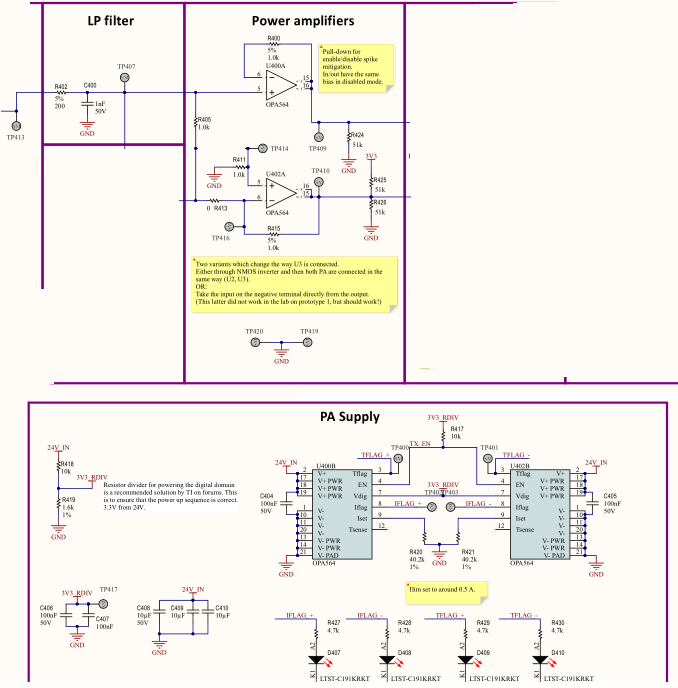
    The complete schematic regarding the OPA564 (I erased some stuff that I have not mounted, hence the schematic looks very messy).


    My input to this schematic page is a 0-1.5V LP-filtered square wave with a frequency around 100-200 kHz.

    What am I missing? Any more ideas why it isn't working? 

    (I made a workaround with a inverting transistor to the - side, but would rather have this simpler schematic working if it is supposed to work.)

  • Hi Peter,

    I am catching up on some of the E2E inquires from the holiday period.

    Closely reviewing your circuit I find two things that may be at the root of your OPA564 issues:

    1. The 3.3 V VDIG (3V3_RDIV) is derived from the V+ (24 V_IN) bus via the R418, R419 voltage divider. That is fine, however, C406 and C407 which total 200 nF and are connected to the 3V3_RDIV line affect the speed at which VDIG rises. Once 24V_IN is applied it takes about 650 us for the 3V3_RDIV line to rise up to the 3 V level. The Applications Information on datasheet Pg. 14 states that the digital supply voltage (VDIG) be applied before the supply voltage to prevent damage to the OPA564. I would not include C406 and C407 in the circuit. Additional, I would use a 5.1 V zener  such as the 1N5231B instead of R419, and bias it with a current of about 5 mA. That would require a change to the R418 value (~3.9 k). I find that brings the VDIG level up quickly compared to an RC circuit.
    2. The IFLAG and TFLAG flags provide CMOS logic voltage levels relative to V-. They have very low current drive capabilities; tens to hundreds of microamps sink/source. The circuit shown above shows they are terminated in a series 10 k resistor, LED load. This is a very low impedance load in comparison to a very high CMOS gate input. This may be affecting the operation of the flags and may be complicated by issue no. 1. 

    Make sure U400A and/or U402A have not been damaged by issue no 1. Otherwise, I do not find any other issues with the schematics.

    Regards, Thomas

    Precision Amplifiers Applications Engineering

  • Hi again,

    I have now finally had some time to work on this part again.

    1. I have tried to use your proposed suggestion, but for some reason my 3.3V voltage is always slower than the 24V its' derived from.. 
    I used a 3.3V zener with 1-5k resistors.

    2. I tried removing all LEDs.

    I have tried supplying the 3.3V (and tried setting it to 5V too) externally, so I am sure that it is settled before 24V, and it makes no difference.

    Also, I have never had problems with the + OP, just the - one.

    I tried a new component, which I never powered with the "wrong timing", and its' showing exactly the same issues...


    I will try to dig deeper into what could be wrong, I am suspecting that I'm missing something with the input/output voltages, because this issue seems to be identical to the old prototype I had, where it worked if I just inverted the input and used the -OPA in a similar fashion as the +OPA. 

    But I would rather not have to invert the signal if this SHOULD work.. I am afraid another underlying issue may go unnoticed if I just fix it in that way..

  • Hello Peter,

    I went to the lab and set the OPA564 in an inverting amplifier configuration similar to what you are using. It used a gain of 10 V/V because the resistors soldered to the board dicated that gain. That shouldn't make a difference in the outcome. I used a single +24 V supply, and applied a 100 kHz, 2 Vpk square-wave to the inverting input resistor and left the output unloaded. I observed that the IFLAG LED in the circuit was activated, but only when the input signal was applied. If the input signal source was removed the IFLAG LED exstinguished.

    Studying the setup I realized that the 100 kHz signal appled to the input had an implitude of 0 to +2 Vpk. That would be a problem for an OPA564 inverting amplifier powered by a single +24 V supply. In that case, the OPA564 would attempt to invert the input signal and output would try to drive the output level below 0 V, which it cannot do unless it is using a dual (+/-Vs) supply. I found that when the output is driven into the negative rail the IFLAG function activates.

    I changed the polarity of the input signal to 0 to -2 Vpk. That is an acceptable condition because the output can swing positive towards +24 V, with the +24 V supply applied. In that case, the IFLAG function was not activated and the op amp functioned normally. The only way I could get it to reactivate was to load the output to the point where the current limit was exceeded. That is the expected behavior for the IFLAG function.

    This wouldn't be an issue for the OPA564 configured as a non-inverting amplifier because the output follows the input. That is why you don't see the issue with the non-inverting side of the circuit.

    Regards, Thomas

    Precision Amplifiers Applications Engineering

  • Oh yes, of course!

    It works perfectly now.

    Still not sure how to handle the VDIG power, I can add your diode solution instead of the resistor one, but my measurements don't look that good with that solution either when it comes to the timing.
  • Hi Peter,

    I do know the OPA564 datasheet is cautious with regard to the OPA564 VDIG to VSPLY timing relationship. I haven't had any problems when using a 1N5231B, 5.1 V zener biased from a resistor connected to VSPLY. However, the zener capacitance inroduces an RC charge characteristic that introduces some time delay which would be nice to avoid.

    Simulations show that the fastest way to bring the E/S pin fom VSPLY is to use a simple resistive divider. The E/S pin capacitance by itself presents only a few picofarads and the RC charge characteristic had with the zener is much reduced timewise. Just make sure that several milliamps of current are used with the resistive divider. Doing so assures that any small capacitances will be charged quickly.

    I think this OPA564 discussion has come to its satisfactory conclusion. I would like to go ahead and close this E2E discussion.

    Regards, Thomas

    Precision Amplifiers Applications Engineering